
Multielement method and device for testing parts with ultrasound

a multi-element, part technology, applied in the direction of measuring devices, analysing solids using sonic/ultrasonic/infrasonic waves, instruments, etc., can solve the problems of not being able to detect an elongated microstructure, elongated microstructure produces a noise, and masks some signals, so as to achieve the effect of minimising the structural nois

Active Publication Date: 2019-11-28
SAFRAN +2
View PDF0 Cites 0 Cited by
  • Summary
  • Abstract
  • Description
  • Claims
  • Application Information

AI Technical Summary

Benefits of technology

The technical effects of this patent text are: a new device and method for ultrasonically testing parts to detect and locate defects and elongate microstructures with high precision. The device and method are simple, effective, and economical. The system can test a part quickly and accurately, providing valuable information for quality control in manufacturing processes.

Problems solved by technology

However, these methods and these devices do not make it possible to detect an elongate microstructure located in a part to be tested.
Yet, a disadvantage of a part comprising an elongate microstructure is that, during a testing of this part with an ultrasound beam, the backscatter of the ultrasound beam with this elongate microstructure produces a noise, called structural noise.
This structural noise interferes with signals coming from the reflection, from the diffusion and / or of the backscatter of the ultrasound beam by the defects located in the part, and masks some of the signals measured during a testing of the part.
This disadvantage is all the more notable when the part to be tested comprises a complex shape or an internal anisotropic structure.
Moreover, the inventors have shown that the geometry of known ultrasound transducers does not make it possible to precisely detect the presence of an elongate microstructure located in a part to be tested.

Method used


Image

  • Multielement method and device for testing parts with ultrasound
  • Multielement method and device for testing parts with ultrasound
  • Multielement method and device for testing parts with ultrasound

Examples


Embodiment Construction

[0055]Below in the description, elements having a design, or identical, similar or comparable functions will be designated by the same reference.

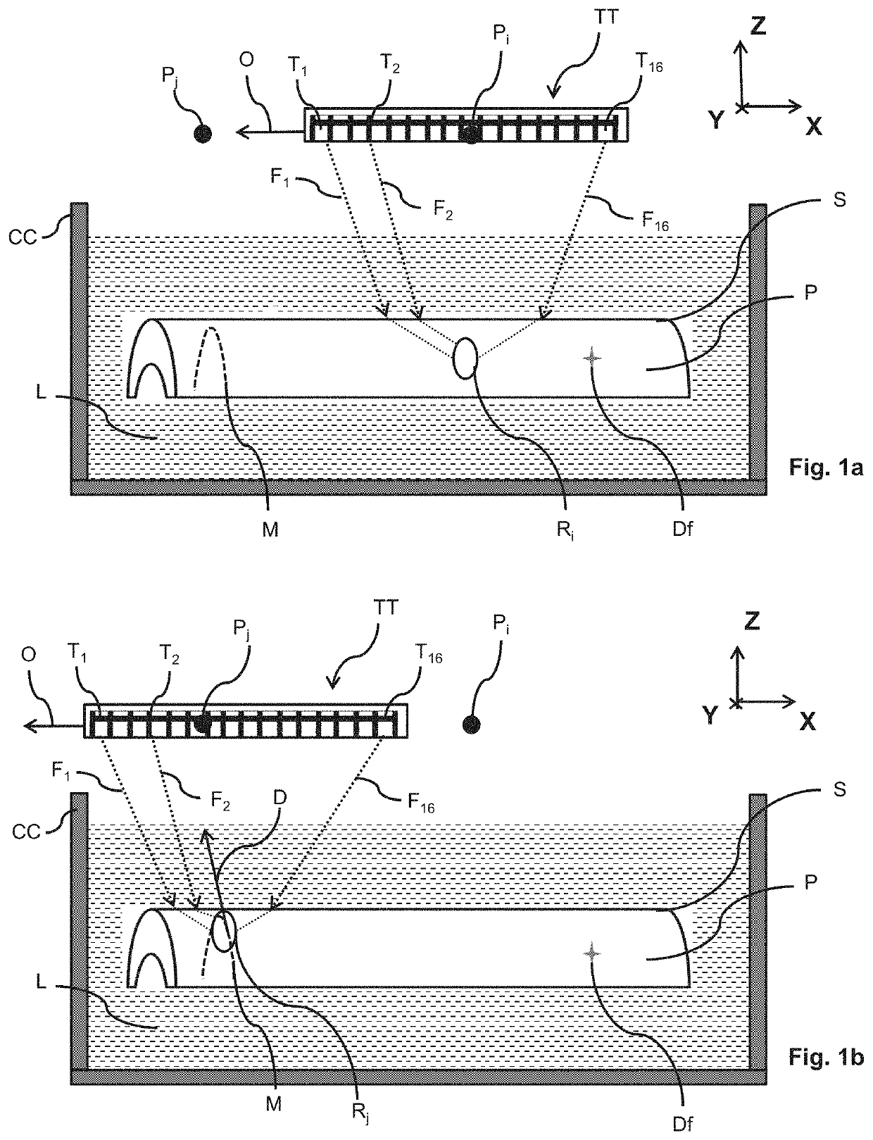
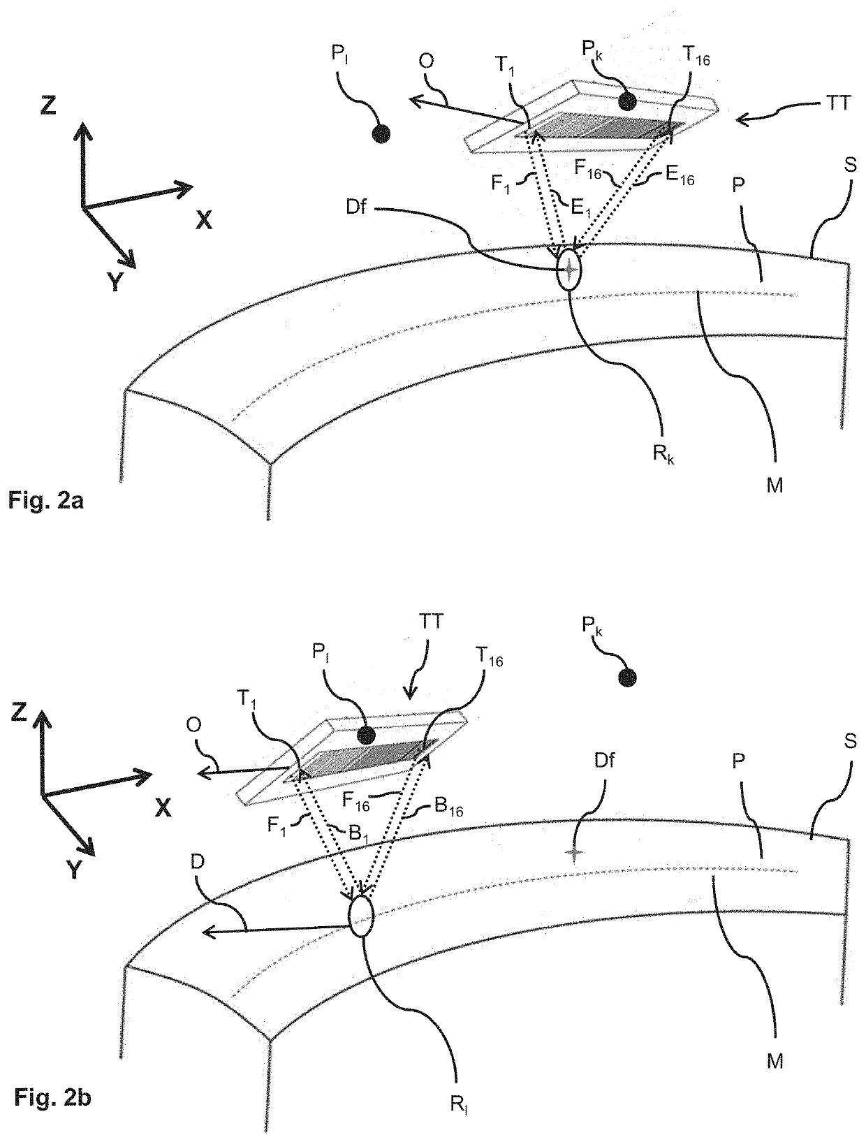
[0056]FIGS. 1a, 1b, 2a and 2b represent schematic views of a method for non-destructively testing a part P using a linear transducer TT according to an embodiment of the invention. In the examples represented, the part P comprises an elongate microstructure M and a defect Df which is located under a surface S of said part P. Furthermore, the part P is a titanium-forged billet, of cylindrical shape, which comprises an internal anisotropic structure leading to an elongate microstructure M along a direction D.

[0057]In a non-limiting manner, the part P can be any type of part, shape and composition. For example, the part P can be a metal part, a composite material part comprising metal fibres, or also a part comprising a single-directional reinforcement oriented along a direction. According to other examples, the part P can be an axisymmetrical...


PUM


Abstract

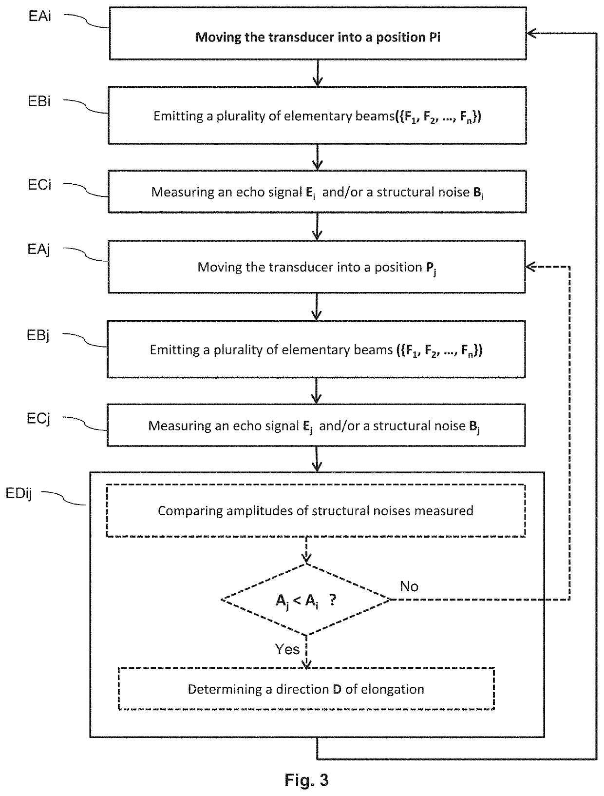
A method for nondestructively testing a part comprising an elongate microstructure is disclosed. The method comprises: moving a linear transducer to a plurality of positions located facing a surface of the part, the linear transducer comprising a plurality of transducer elements that are aligned along a main direction; emitting a plurality of elementary ultrasonic beams, each of the plurality of elementary ultrasonic beams being emitted by each of the plurality of transducer elements in the direction of the surface; measuring a plurality of echo signals and a plurality of structural noises, each of the plurality of echo signals and each of the plurality of structural noises being measured by each of the plurality of transducer elements, each of the echo signals resulting from the backscatter of the elementary ultrasonic beams by a defect under the surface of the part, and each of the structural noises resulting from the backscatter of the elementary ultrasonic beams by the elongate microstructure; and determining a direction of elongation of the elongate microstructure when an amplitude of one among the plurality of measured structural noises is minimal in the plurality of positions. Furthermore, a non-destructive testing system for implementing the testing method is disclosed.

Description

BACKGROUND OF THE INVENTION[0001]The present invention relates to the general field of ultrasound transducers with multiple elements. In particular, the present invention applies to the non-destructive testing of parts comprising an elongate microstructure.[0002]In the field of aeronautics, it is important to test all forged parts intended to be mounted in an aircraft. These parts are constituted of a material, for example titanium or a titanium alloy, comprising a crystalline structure and a microstructure. By definition, the crystalline structure of a part defines the structure of this part at a scale of around one tenth of a nanometre. The microstructure of a part defines the structure of this part at a scale of between one nanometre and one centimetre.[0003]The crystalline structure of a part is tested using methods based on the diffraction of electromagnetic waves, for example the diffraction of X-rays. The microstructure of a part is tested using methods based on the reflectio...

Claims


Application Information

Patent Timeline
IPC IPC(8): G01N29/04G01N29/22G01N29/265G01N29/24G01N29/32G01N29/11G01N29/48
CPCG01N29/043G01N29/11G01N29/225G01N29/2456G01N29/265G01N29/48G01N2291/015G01N2291/0234G01N2291/0289G01N2291/044G01N2291/106G01N29/221G01N29/2437G01N29/32G01N2291/101G01N2291/269
Inventor BAELDE, AURÉLIENJENSON, FRÉDÉRICFINK, MATHIASLAURENT, JÉRÔMEPRADA, CLAIRE
Owner SAFRAN
Learn More