Image pickup apparatus having auto day-night function, control method therefor, and storage medium storing control program therefor
- Summary
- Abstract
- Description
- Claims
- Application Information
AI Technical Summary
Benefits of technology
Problems solved by technology
Method used
Image
Examples
first embodiment
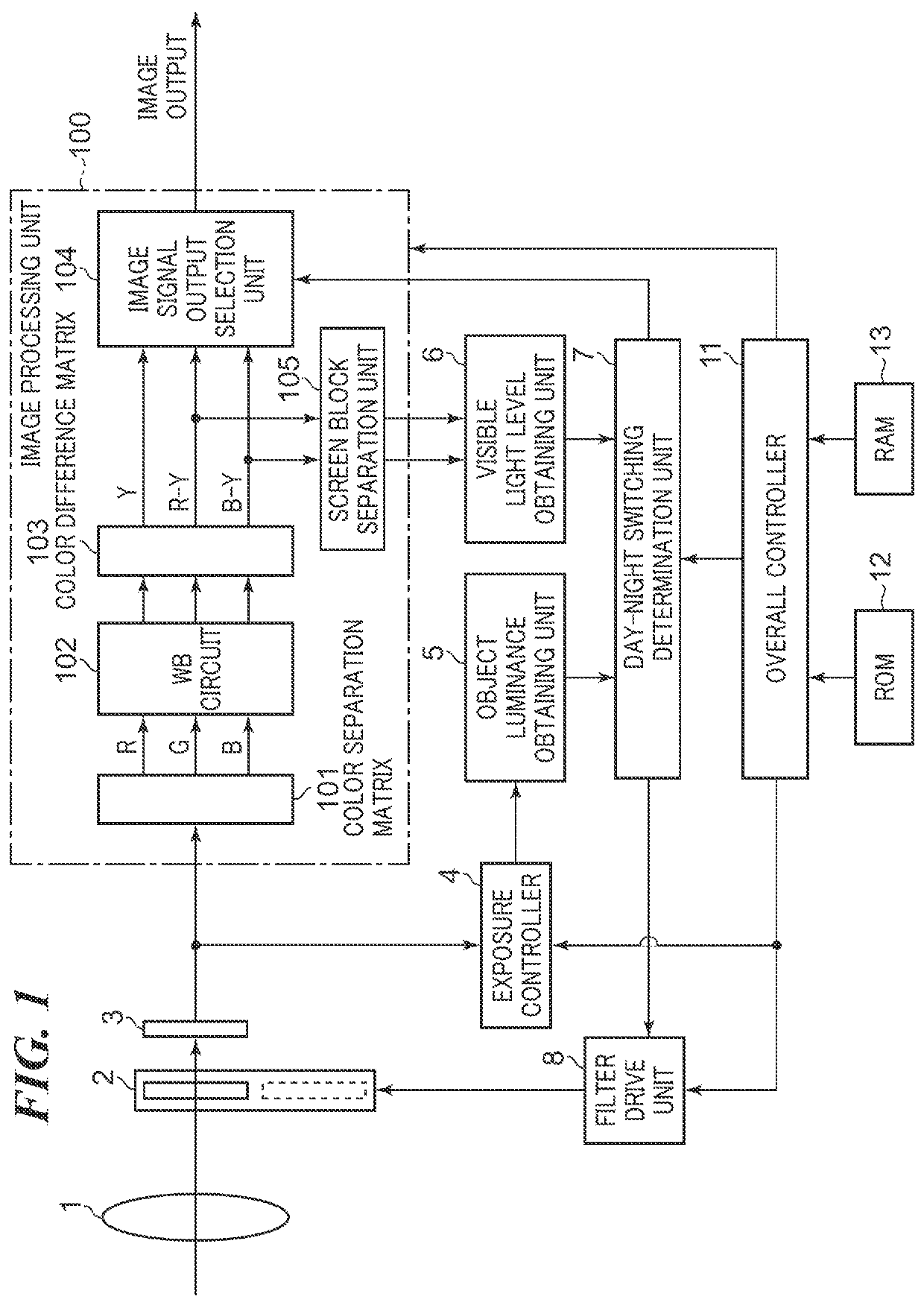
[0027]FIG. 1 is a block diagram schematically showing a configuration of an example of an image pickup apparatus according to the present invention.
[0028]The illustrated image pickup apparatus is a digital camera (hereinafter referred to as a “camera” simply), for example, and has an overall controller (a CPU) 11. The overall controller 11 develops a program stored in a nonvolatile memory (ROM) 12 to a volatile memory (RAM) 13 and runs the program to control the entire camera. It should be noted that the RAM 13 is used also as a work area of the overall controller 11.
[0029]Object light that enters through an image pickup optical system 1 forms an optical image on an image sensor 3. Then, the image sensor 3 outputs an image signal corresponding to the optical image. The image signal concerned is output to an exposure controller 4 and an image processing unit 100. An infrared cut filter 2 provided with an attenuation area that reduces intensity of light in a wavelength range correspon...
second embodiment
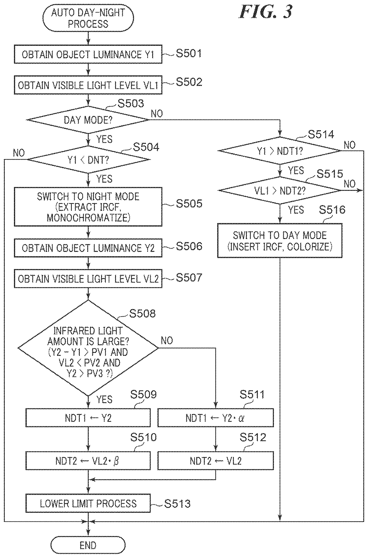
[0086]FIG. 4 is a flowchart for describing an example of the auto day-night process performed by the camera according to the present invention. It should be noted that the steps in FIG. 4 that are the same as the steps in the flowchart in FIG. 3 are indicated by the same reference numbers and their descriptions are omitted.
[0087]When it is determined that there is much infrared light (YES in the step S508), the day-night switching determination unit 7 turns ON an infrared flag (validates infrared information) in step S601. Furthermore, this infrared flag is used for storing the determination result of the process in the step S508. Then, the day-night switching determination unit 7 proceeds with the process to the step S510.
[0088]In the meantime, when there is little infrared light (NO in the step S508), the day-night switching determination unit 7 turns OFF the infrared flag (invalidates the infrared information) in step S602. Then, the day-night switching determination unit 7 proce...
third embodiment
[0096]Subsequently, one example of a camera according to the present invention will be described.
[0097]FIG. 5 is a block diagram schematically showing a configuration of the example of the camera according to the third embodiment of the present invention. It should be noted that the same reference numerals are assigned to components in FIG. 5 that are the same as the components of the camera shown in FIG. 1.
[0098]The illustrated camera has an infrared-light illumination device 701, infrared illumination setting unit 702, and infrared illumination controller 703. Then, the infrared illumination controller 703 is controlled by the overall controller 11. The illustrated camera irradiates the object with the infrared light using the infrared-light illumination device 701 and is able to photograph brightly in the night mode even in a low illumination state.
[0099]A user selects whether to use the infrared-light illumination device 701 through the infrared illumination setting unit 702. Th...
PUM
 Abstract
Description
Claims
Application Information
 - R&D
- Intellectual Property
- Life Sciences
- Materials
- Tech Scout
- Unparalleled Data Quality
- Higher Quality Content
- 60% Fewer Hallucinations
Browse by: Latest US Patents, China's latest patents, Technical Efficacy Thesaurus, Application Domain, Technology Topic, Popular Technical Reports.
© 2025 PatSnap. All rights reserved.Legal|Privacy policy|Modern Slavery Act Transparency Statement|Sitemap|About US| Contact US: help@patsnap.com


