
Method and system for calibration of UV light sources

a technology calibration method, which is applied in the field of method and system for calibration of uv light source, can solve the problems of human error, incomplete decontamination, unfavorable uv lamp calibration, etc., and achieve the effect of accurately determining thermal equilibrium, improving uv lamp calibration, and increasing the output decay factor of diodes

Active Publication Date: 2019-12-05
PHOSEON TECHNOLOGY INC
View PDF0 Cites 1 Cited by
  • Summary
  • Abstract
  • Description
  • Claims
  • Application Information

AI Technical Summary

Benefits of technology

The patent describes a way to improve the calibration of UV lamps by using narrow-band UVC photodiodes and temperature regression analysis. This approach can be used to calibrate the lamp across a wide range of operational conditions without exposing an operator to UV radiation. The technical effect is to reduce human error contributions to the calibration routine and improve the accuracy and efficiency of lighting systems.

Problems solved by technology

As an example, if the SLM channels are not calibrated prior to use in curing photosensitive adhesives and media, the target irradiance may not be achieved across the irradiated media, resulting in uneven and / or incomplete curing.
As another example, if the SLM channels are not calibrated prior to use in UVGI, the target irradiance may not be achieved across the irradiated laboratory equipment, resulting in incomplete decontamination.
However, there are various potential issues with such an approach.
The issues may include human error, reduced repeatability of temperature and environmental factors, and the potential for operator exposure to dangerous wavelengths of UV light.
Both adjustment methods can introduce potential error into the process, as all adjustments and the irradiance readings these adjustments rely on are performed and observed by a human operator.
Furthermore, UVC wavelength diodes are in their infancy, having just come out of research and development.

Method used


Image

  • Method and system for calibration of UV light sources
  • Method and system for calibration of UV light sources
  • Method and system for calibration of UV light sources

Examples


Embodiment Construction

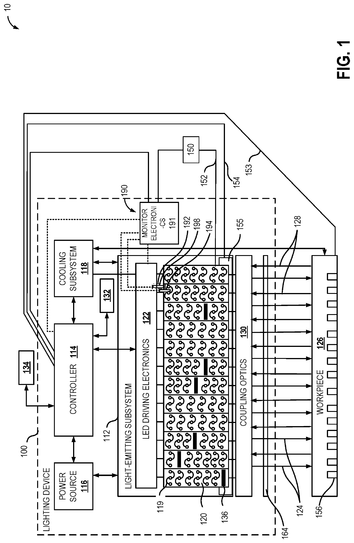
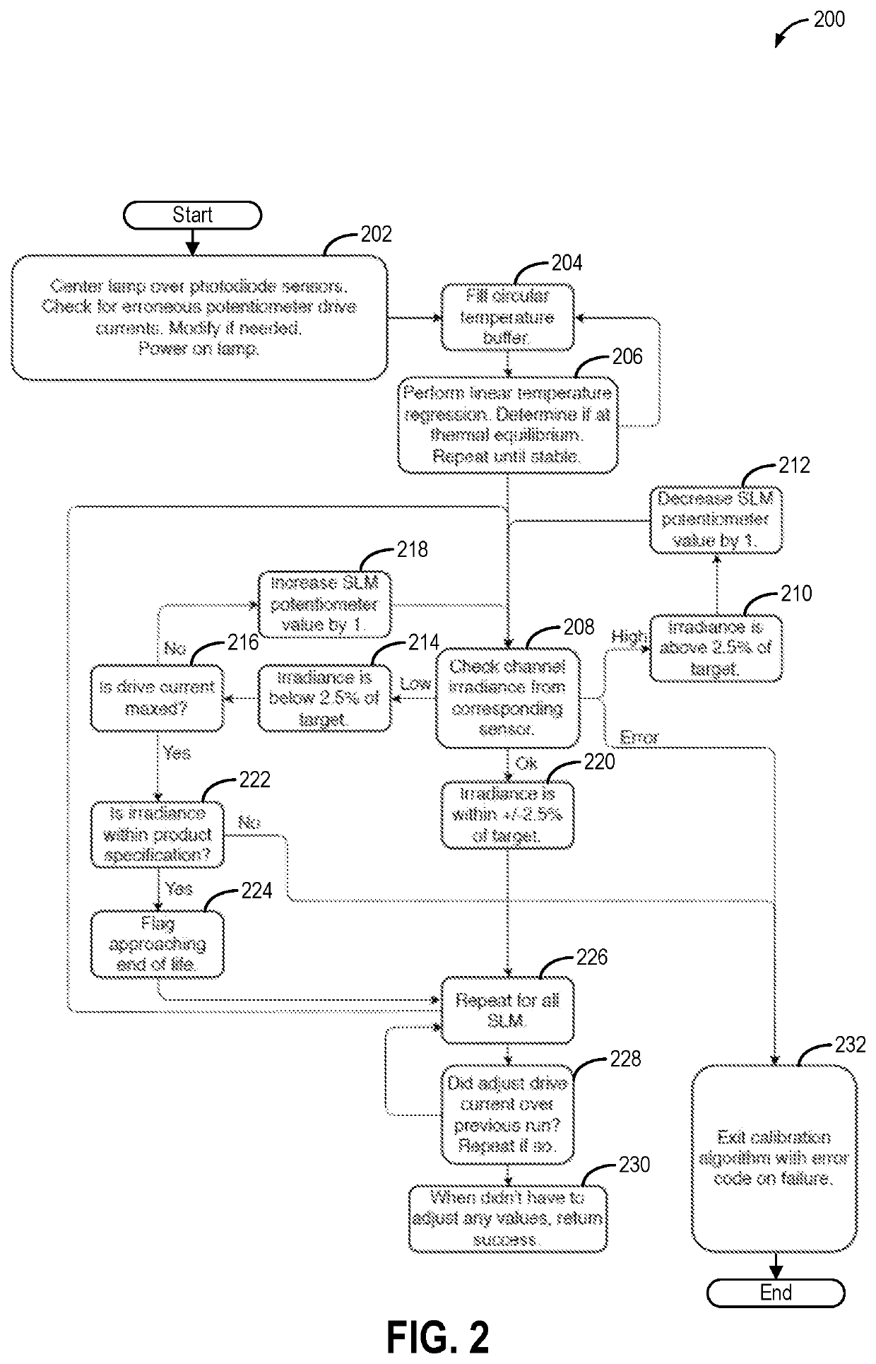
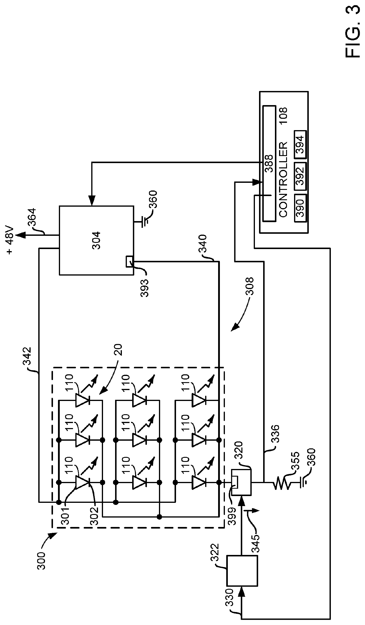
[0018]The present description is related to a semiconductor lighting system, such as the lighting system of FIG. 1. The lighting system may be operated according to the method of FIG. 2 to enable each of the light arrays of the lighting system to be equalized with one another and calibrated. During the calibration, a drive current directed to the solid-state lighting system may be adjusted via a circuit, such as the circuit of FIG. 3. A prophetic example of semiconductor lighting system calibration is shown at FIG. 4. Once calibrated, the semiconductor lighting system may be used to decontaminate a microplate, such as shown in FIG. 5.

[0019]Referring now to FIG. 1, it illustrates a block diagram for an example configuration of a lighting device 100 that may be included in an irradiation system 10. In one example, lighting device 100 may comprise a light-emitting subsystem 112, a controller 114, a power source 116 and a cooling subsystem 118. The light-emitting subsystem 112 may compr...


PUM

PropertyMeasurementUnit
thresholdaaaaaaaaaa
voltageaaaaaaaaaa
voltage dropaaaaaaaaaa

Abstract

Methods and systems are provided for calibrating a UV lamp having a plurality of arrays or channels of light emitting diodes. The calibration involves adjusting a drive current applied to the UV lamp based on an actual irradiance output by its light-emitting diodes relative to a target irradiance. The calibration is selectively performed when a stabilized temperature condition of the lamp is met.

Description

CROSS REFERENCE TO RELATED APPLICATIONS[0001]The present application claims priority to U.S. Provisional Application No. 62 / 678,769, entitled “METHOD AND SYSTEM FOR CALIBRATION OF UV LIGHT SOURCES”, and filed on May 31, 2018. The entire contents of the above-listed application are hereby incorporated by reference for all purposes.FIELD[0002]The present description relates generally to methods and systems for concurrently calibrating a plurality of UV light sources.BACKGROUND / SUMMARY[0003]Solid-state lighting devices have many uses in industrial applications. For example, ultraviolet (UV) lighting devices have become fairly common for curing photo sensitive media such as coatings, including inks, adhesives, preservatives, etc. Curing time of these photo sensitive media may be controlled via adjusting intensity of light directed at the photo sensitive media or the amount of time that the photo sensitive media is exposed to light from the solid-state lighting device. As another example...

Claims


Application Information

Patent Timeline
Patent Type & Authority Applications(United States)
IPC IPC(8): A61L2/10H05B33/08A61L2/24H05B44/00
CPCA61L2202/14A61L2/24A61L2/10H05B33/0851A61L2202/11A61L2202/23H05B45/18H05B45/12G01J2001/444
Inventor LAMOUREUX, TEGAN
Owner PHOSEON TECHNOLOGY INC
Learn More