Drive control device

a control device and drive technology, applied in the direction of electric devices, propulsion parts, transportation and packaging, etc., can solve the problems of significant deterioration of accelerating performance or inability to run upslope, malfunction of a portion of the bearing or the speed reducer, and increase the cost of production, so as to reduce the speed of rotation, and extract the limited torque value.

Inactive Publication Date: 2019-12-26
NTN CORP
View PDF3 Cites 0 Cited by
  • Summary
  • Abstract
  • Description
  • Claims
  • Application Information

AI Technical Summary

Benefits of technology

[0017]In this configuration, the torque limitation module 26 can easily extract the limited torque value by searching the map Mp with the oil temperature and the rotation speed of the motor. The limited torque value enables a motor torque to be limited.
[0018]The motor 6, a wheel bearing 4 rotationally supporting the wheel 2, and the speed reducer 7 for reducing the speed of the rotation of the motor 6 to transmit the reduced rotation to the wheel bearing 4, may form an in-wheel motor drive device MM. The in-wheel motor drive device IWM is at least partially exposed to the outside of the vehicle and is close to the ground. As such, the in-wheel motor drive device is used under severer condition, and thus the oil temperature more easily becomes low, than in a motor drive device of a so-called on-hoard type. Even in a vehicle including such in-wheel motor drive devices IWM, a problem such as excessive wear can be prevented from occurring on the speed reducer or the like by limiting the torque of the motor 6 in accordance with the oil temperature and the rotation speed of the motor. Also, the minimal necessary acceleration performance and upslope-running performance can be ensured.
[0019]A drive control system according to the present invention may be a drive control system including two or more drive control devices 20 each of which is described above, the vehicle being mounted with the two or more drive control devices 20, in the vehicle left and right wheels being driven independently, wherein the two or more drive control devices 20 may share, or may separately have, the torque limitation module 26, and the shared torque limitation module 26 or at least one of the separate torque limitation module 26 may ...

Problems solved by technology

If the electric motor is rotated at a high speed and oil supply is not sufficient, a malfunction can occur in a portion of the bearing or the speed reducer.
If a small limited torque value, i.e...

Method used


Image

  • Drive control device
  • Drive control device
  • Drive control device

Examples


second embodiment

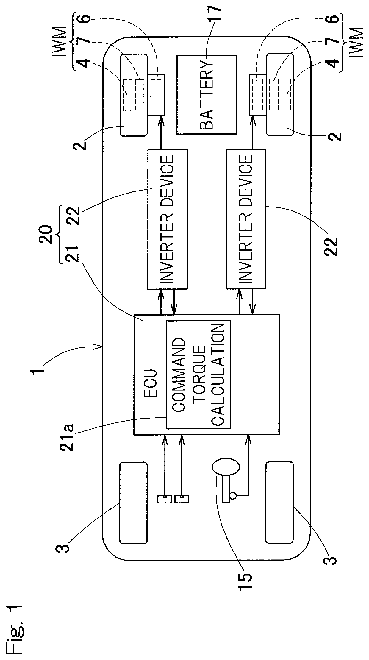
[0062]A drive control device and a process by the drive control device will be described as follows with reference to FIG. 4. The torque limitation module 26 may extract limited torque values on the left and right, and set, as a limited torque value for both of the motors 6 and 6 for respective left and right wheels 2 and 2, a limited torque value that is smaller between the limited torque values for the motors 6 and 6 for these respective left and right drive wheels 2 and 2 (FIG. 1). Specifically, as showm in FIG. 4 and FIG. 7, the determination section 29 determines whether or not at least one of the oil temperatures detected by the oil temperature acquisition device Sa for the left and right wheels 2 and 2 is equal to or lower than the threshold value (step b1). If both oil temperatures are determined to be higher than the threshold value (step b1; No), the torque limitation module 26 sets the maximum torque as the limited torque value for both wheels (step b2). Thereafter, this...

third embodiment

[0065]A drive control device and a process by the drive control device will be described as follows with reference to FIG. 4. The torque limitation module 26 may extract a limited torque value on the basis of: an oil temperature that is lower between oil temperatures respectively sensed by the oil temperature acquisition devices Sa for the respective left and right wheels (hereinafter, referred to simply as “left-wheel oil temperature” and “right-wheel oil temperature”, respectively); and a rotation speed that is higher between rotation speeds respectively detected by the rotation speed detection modules 28 for the respective left and right wheel (hereinafter, referred to simply as “left-wheel rotation speed” and “right-wheel rotation speed”, respectively). Specifically, as shown in FIG. 4 and FIG. 8, if at least one of the left-wheel and right-wheel oil temperatures is determined to be equal to or lower than the threshold value (step b1; Yes), the torque limitation module 26 deter...


PUM


Abstract

Provided is a drive control device (20) for controlling a motor (6) of a vehicle including the motor (6) for driving the vehicle, a speed reducer (7) for reducing the speed of rotation of the motor (6) to transmit the reduced rotation to a wheel, and a mechanism for supplying lubricating oil to the motor (6) and the speed reducer (7). The device (20) includes an oil temperature sensor (Sa) for obtaining the temperature of the lubricating oil, and a rotation speed detection module (28) for detecting the rotation speed of the motor (6). The device (20) further includes a torque limitation module (26) for limiting a torque to be generated in the motor (6), based on the obtained oil temperature and the detected rotation speed of the motor (6), when the oil temperature obtained by the sensor (Sa) is equal to or lower than a predetermined temperature.

Description

CROSS REFERENCE TO THE RELATED APPLICATION[0001]This application is a continuation application, under 35 U.S.C. 111(a), of international application No. PCT / JP2018 / 009260, filed Mar. 9, 2018, which claims Convention priority to Japanese patent application No. 2017-046153, filed Mar. 10, 2017, the entire disclosure of which is herein incorporated by reference as a part of this application.BACKGROUND OF THE INVENTIONField of the Invention[0002]The present invention relates to a drive control device in which necessary torque limitation is performed and loads on machine elements such as a bearing and a gear is reduced at low temperature.Description of Related Art[0003]An in-wheel motor drive device including an electric motor, a wheel bearing, and a speed reducer has been proposed (Patent Document 1). The speed reducer described in Patent Document 1 is lubricated with lubricating oil that is pressure-fed by an oil pump. In the invention described in Patent Document 1, when the temperatu...

Claims


Application Information

Patent Timeline
IPC IPC(8): B60K11/02B60L3/00B60L15/20B60W50/038B60K7/00B60K17/04B60W10/30
CPCB60K7/0007B60L15/20B60W10/30B60W2710/083B60K17/046B60L3/0061B60K11/02B60W50/038B60W2710/081B60W2510/083B60L2240/421B60L2240/423B60L3/00B60L9/18Y02T10/72
Inventor KANDA, TAKESHI
Owner NTN CORP
Why Eureka
Try Eureka