
Siding attachment system

a technology of attachment system and siding, which is applied in the direction of covering/lining, construction, building construction, etc., can solve the problems of affecting the cutting effect of the bracket, the tendency of the siding to expand and contract with the temperature change, and the general time-consuming. to achieve the effect of convenient cutting the brack

Active Publication Date: 2019-12-26
ONEAL JERRY D
View PDF4 Cites 0 Cited by
  • Summary
  • Abstract
  • Description
  • Claims
  • Application Information

AI Technical Summary

Benefits of technology

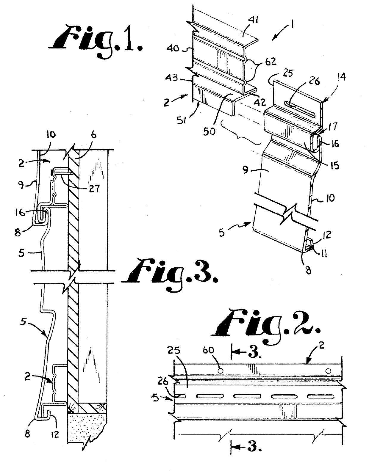
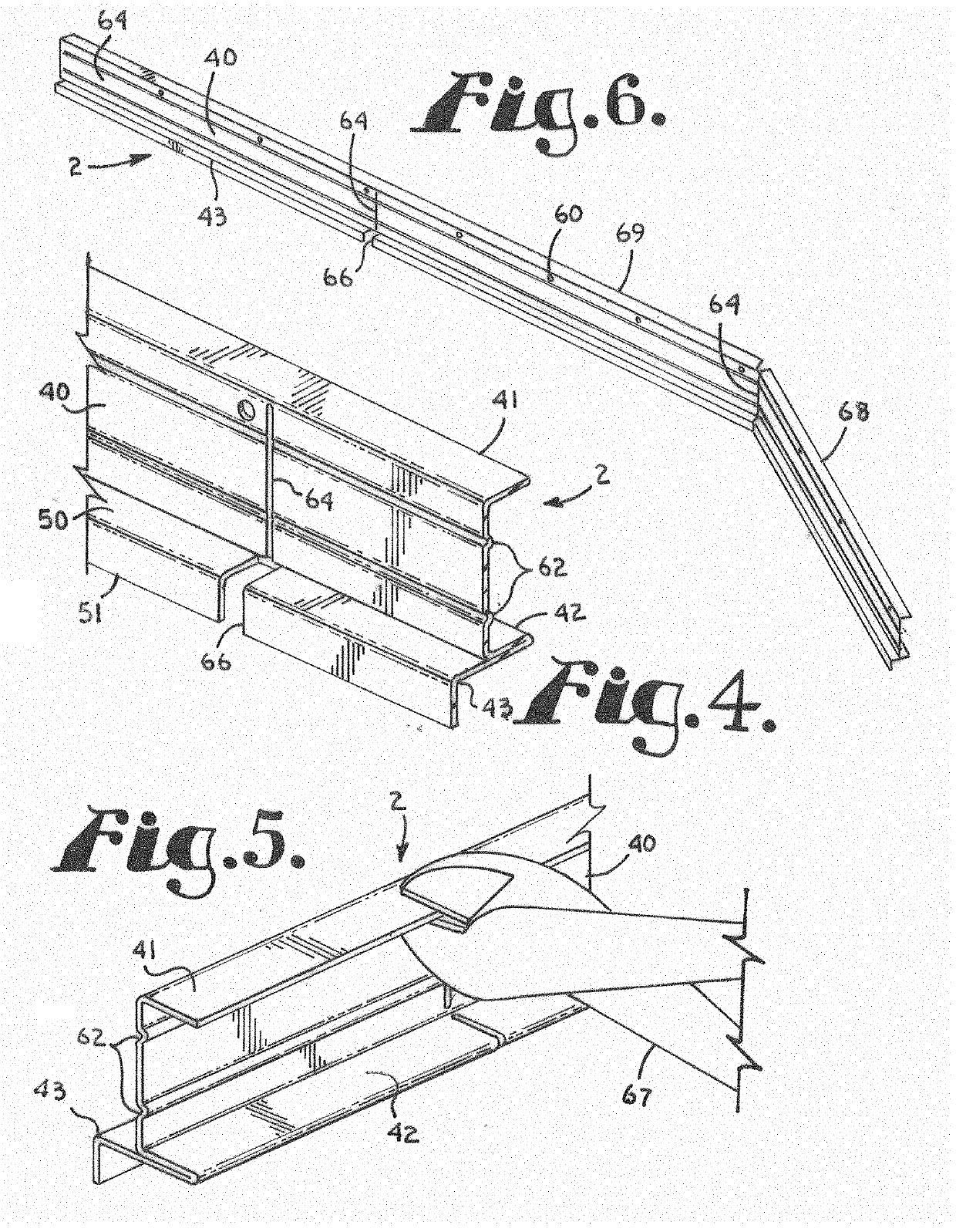
The patent is about an improvement to a siding support bracket that allows for easier cutting and adjustment to different lengths. The bracket includes a vertical web with holes for receiving fasteners, support legs, and a siding support shoulder with a horizontal and vertical leg. The improvement includes adding score lines and notches in the web and legs, which makes it easier to cut the bracket to a desired length. Additionally, a stiffening rib can be added to provide extra strength to the bracket. This makes it more stable and durable for use in construction.

Problems solved by technology

One problem common to both metal and vinyl siding is its tendency to expand and contract with changes in temperature.
The primary problem with such nail slots is the difficulty in driving a nail or other fastener through the nail slots without fastening the nail too tight thereby preventing slidable movement.
One drawback to such clips is that in use it is generally time consuming to slide a large number of clips onto long sections of siding from the ends to provide the appropriate number of clips for supporting the siding.
Further, it is then difficult to maneuver the siding with the clips secured thereto prior to securement to the building without having the clips slide off the end of the siding.
An additional problem associated with conventional methods for hanging siding which is not corrected through use of siding clips is the tendency of vinyl siding to conform to irregularities or bows of a wall.
As a building settles and ages, movement of the foundation and warping, racking or twisting of wood framing members through weathering and natural drying processes results in irregularities and distortions of the wall surface of the building.
In addition, other factors, such as sloppy construction may cause distortion of the wall surface of a building such that the surface is not flat and is wavy or undulates.
Current fastening systems for siding are inadequate to prevent the siding from conforming to such irregularities in the shape of building walls.
Although metal siding tends to be more rigid than vinyl siding, sections of metal siding spanning inward bows on a wall on which it is hung are insufficiently rigid to prevent indentation and permanent deformation of the siding when pressure is exerted against the section of siding spanning such an inward bow.
Existing siding attachment systems do not provide sufficient additional rigidity to prevent such permanent deformation.
Another drawback of existing siding attachment systems including nailing and the use of clips is uneven sagging.
Over time the siding tends to sag.
Over time the unsupported sections of the siding panel will droop or sag further than the supported sections resulting in an uneven, wavy appearance.
However, some siding installers have resisted using the bracket due to the added cost of materials and labor for installing the bracket before attachment of the siding to the bracket.
The siding support bracket is also not adapted for use in installations in which foam insulating panels are to be installed behind the siding.

Method used


Image

  • Siding attachment system
  • Siding attachment system
  • Siding attachment system

Examples


Embodiment Construction

[0026]As required, detailed embodiments of the present invention are disclosed herein; however, it is to be understood that the disclosed embodiments are merely exemplary of the invention, which may be embodied in various forms. Therefore, specific structural and functional details disclosed herein are not to be interpreted as limiting, but merely as a basis for the claims and as a representative basis for teaching one skilled in the art to variously employ the present invention in virtually any appropriately detailed structure. The drawings constitute a part of this specification and include exemplary embodiments of the present invention and illustrate various objects and features thereof.

[0027]Certain terminology will be used in the following description for convenience in reference only and will not be limiting. For example, the words “upwardly,”“downwardly,”“rightwardly,” and “leftwardly” will refer to directions in the drawings to which reference is made. The words “inwardly” a...


PUM


Abstract

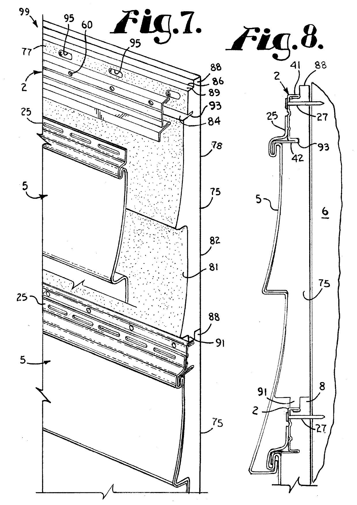
A siding assembly includes a siding panel and an insulating panel securable to a wall using a siding attachment member. The siding attachment member includes openings extending therethrough in equally spaced relationship that align with slots formed in the foam panel. The spacing between centers of the foam panel slots corresponds to the spacing between centers of the openings in the attachment member. The slots in the foam panels are sufficiently wide to allow the foam panel to slide relative to the fasteners securing the foam panel to a wall. The siding attachment member may comprise a bracket with legs projecting rearward from a web and a siding support shoulder formed at a lower end of the web. Lines of weakness in the web and aligned notches in the shoulder facilitate cutting the bracket to a desired length. Reinforcement ribs are formed in the bracket web.

Description

BACKGROUND OF THE INVENTIONField of the Invention[0001]The present invention relates to the attachment of vinyl or metal siding to a building.Description of the Related Art[0002]Metal and plastic siding are commonly used as an imitation and substitute for wooden lap siding. The metal and plastic siding provide the appearance of wood siding while generally having a longer life span and require less maintenance. Metal siding is typically formed of aluminum or steel while plastic siding is conventionally formed of extruded sections of thermoplastic polyvinyl chloride which is commonly referred to as vinyl siding. In both types of siding, the bottom margin of each panel is typically bent inwardly and then upwardly to form a longitudinal channel with an upstanding inner leg. The top portion of each panel is formed to provide an outwardly and downwardly projecting longitudinal lip corresponding to the channel running along the bottom of the panel positioned thereabove. A securement flange...

Claims


Application Information

Patent Timeline
Patent Type & Authority Applications(United States)
IPC IPC(8): E04F13/08
CPCE04F13/0803E04F13/0864E04F13/0878E04F13/0876E04F13/0817
Inventor O'NEAL, JERRY D.
Owner ONEAL JERRY D
Learn More