Facility inspection system and facility inspection method

a technology for inspection systems and facilities, applied in television systems, scene recognition, instruments, etc., can solve problems such as passenger and public danger, failure of other railroad electrical equipment,

Active Publication Date: 2019-12-26
HITACHI HIGH TECH SOLUTIONS CORP
View PDF0 Cites 5 Cited by
  • Summary
  • Abstract
  • Description
  • Claims
  • Application Information

AI Technical Summary

Benefits of technology

[0011]This disclosure can prevent the normal part from being detected as the abnormal part caused by the deviation in the alignment due to the presence / absence of the moving object in detecting the abnormal part in the surrounding environment of the vehicle moving on the track (for example, the rail). Further features pertain to this disclosure will become clear by descriptions in this Description and attached drawings. Problems, configurations, and effects other than ones described above will be made apparent from the following

Problems solved by technology

When a damage 15B occurs on a hanger that hangs the overhead line, the overhead line droops down to cause a damage on the railroad vehicle passed by and a failure of other railroad electrical equipment due to a ground fault.
When a part of a member that supports the beam and the overhead line drops off, a deformation, a collapse, or the like of this facility possibly brings danger to a passenger and the public.

Method used


Image

  • Facility inspection system and facility inspection method
  • Facility inspection system and facility inspection method
  • Facility inspection system and facility inspection method

Examples


first embodiment

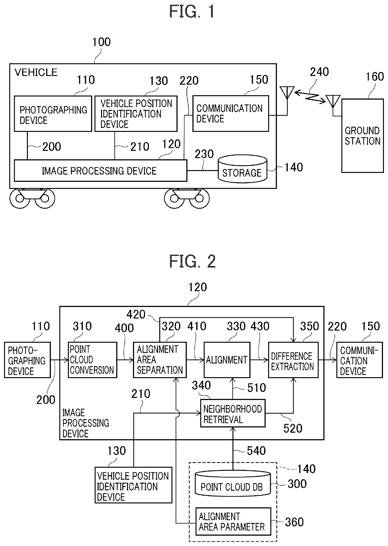
[0031]FIG. 1 is a drawing describing a configuration of a railroad facility inspection system according to the first embodiment. The railroad facility inspection system includes a vehicle 100 and a ground station 160.

[0032]The vehicle 100 includes a photographing device 110, an image processing device 120, a vehicle position identification device 130, a storage (storage device) 140, and a communication device 150. As described above, the vehicle 100 may be the test vehicle, a road railer, and similar vehicle in addition to the business vehicle insofar as the vehicle 100 can move along a railroad rail.

[0033]The photographing device 110 obtains a range image 200 of the surrounding environment of the vehicle 100, and outputs the range image 200 to the image processing device 120. The photographing device 110 only needs to include a device configured to obtain the range image, for example, a stereo camera and a three-dimensional sensor of a Time-of-Flight (TOF) method. For example, the ...

second embodiment

[0070]FIG. 10 is a drawing describing a configuration of an image processing device 120 according to the second embodiment. Identical reference numerals are assigned for the components described in the above-described first embodiment and the descriptions are omitted.

[0071]The image processing device 120 includes the point cloud conversion unit 310, an alignment area separation unit 910, the alignment unit 330, the neighborhood retrieval unit 340, the difference extraction unit 350, and an area retrieval unit 930. An area DB 920 is a database implemented to the storage 140.

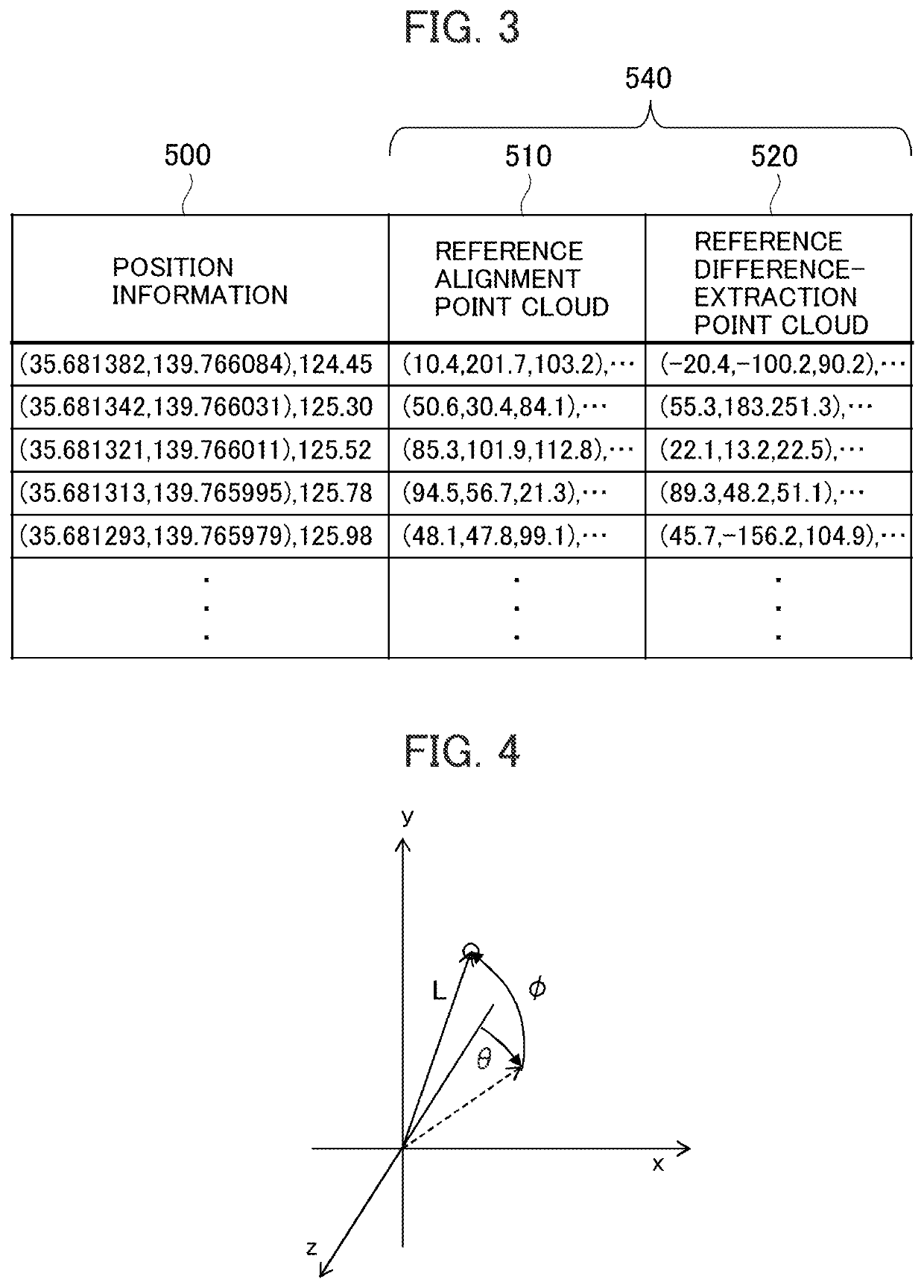
[0072]FIG. 11 illustrates an exemplary area DB 920. The area DB 920 includes reference position information 1010 and alignment area candidate information 1020 as configuration items. The area DB 920 includes the information on the point clouds as candidates of the alignment area on respective reference positions (reference position information 1010) on the rail. The alignment area separation unit 320 of the first ...

third embodiment

[0087]FIG. 14 is a drawing describing a configuration of an image processing device 120 according to the third embodiment. Identical reference numerals are assigned for the components described in the above-described first embodiment and the descriptions are omitted.

[0088]The image processing device 120 further includes an alignment area choosing unit 1310 in addition to the configuration of FIG. 2. The alignment area choosing unit 1310 receives the three-dimensional point cloud 400 as the input information from the point cloud conversion unit 310, and obtains candidate area information 1300 stored in the storage 140 as the input information. The candidate area information 1300 includes the information on a plurality of candidate areas and information on priority orders of the respective candidate areas. The alignment area choosing unit 1310 determines a count of three-dimensional points in each candidate area of the three-dimensional point cloud 400 detected via the photographing d...


PUM


Abstract

A facility inspection system prevents a normal part from being detected as an abnormal part caused by a deviation in an alignment due to a presence / absence of a moving object in detecting the abnormal part in a surrounding environment of a vehicle moving on a track. The system includes a photographing device, storage device, separation unit, an alignment unit, and a extraction unit. The photographing device photographs the surrounding environment of the moving vehicle. The storage device stores a reference alignment point cloud and a reference difference-extraction point cloud for each position on the track. The separation unit separates the alignment point cloud from a three-dimensional point cloud. The alignment unit aligns the reference alignment point cloud and the alignment point cloud and outputs alignment information. The extraction unit extracts a difference between the three-dimensional point cloud deformed based on the alignment information and the reference difference-extraction point cloud.

Description

TECHNICAL FIELD[0001]This disclosure relates to a facility inspection system and a facility inspection method.BACKGROUND ART[0002]There are various railroad facilities such as a substation, a beam, and an overhead line around a railroad rail. When foreign objects adhere to these facilities or damages are caused on the facilities, a railroad operation is interfered. FIG. 16 illustrates examples of the adherence of the foreign objects to the railroad facility and the damage of the railroad facility. When a flying object 15A such as a polyethylene bag and clothes adheres to the overhead line, a damage is caused on a railroad vehicle passed by. When a damage 15B occurs on a hanger that hangs the overhead line, the overhead line droops down to cause a damage on the railroad vehicle passed by and a failure of other railroad electrical equipment due to a ground fault. When a part of a member that supports the beam and the overhead line drops off, a deformation, a collapse, or the like of t...

Claims


Application Information

Patent Timeline
Patent Type & Authority Applications(United States)
IPC IPC(8): G06K9/00G01B11/00B60M1/28B61L15/00B61L23/00
CPCG06K9/00791G06K9/0063B61L23/00B60M1/28B61L15/0081G01B11/002B61L23/041H04N7/188H04N7/18G06V20/56G06V20/13
Inventor CHIHARA, NOBUHIROHONDA, MASAHIKOKISHI, TOSHIHIDESHINBO, MASASHIHORIE, KIYOTAKE
Owner HITACHI HIGH TECH SOLUTIONS CORP
Why Eureka
Try Eureka