Combined inductive and switched capacitive power supply conversion

a technology of switching capacitors and power supply, which is applied in the direction of power conversion systems, dc-dc conversion, instruments, etc., can solve the problems of increasing power loss, requiring large amounts of power, and affecting the supply of such power

Inactive Publication Date: 2019-12-26
ENDURA IP HLDG LTD +1
View PDF5 Cites 7 Cited by
  • Summary
  • Abstract
  • Description
  • Claims
  • Application Information

AI Technical Summary

Benefits of technology

[0010]Some embodiments in accordance with aspects of the invention provide a DC-DC converter, comprising: an inductive power conversion stage comprising a high side switch and a low side switch, coupled in series between an input voltage and a lower voltage, and an inductor having a first end coupled to a node between the high side switch and the low side switch; a switched capacitor converter coupled between a second end of the inductor and the lower voltage, the switched capacitor converter comprising a plurality of capacitor and a plurality of switches, the switches operable to have the switched capacitor converter downconvert a voltage provided at the second end of the inductor by a fixed ratio, the switched capacitor converter including sufficient inductances to allow for transfer of charge during switching without non-adiabatic loss.

Problems solved by technology

The provision of such power may face many complexities.
Complicating matters, some devices may be powered by batteries having relatively small capacities, while the devices themselves, at least at various times, may require large amounts of power.
Provision of power at voltage levels significantly lower than supply voltage levels may result in increased power losses as the voltage level is stepped down.

Method used


Image

  • Combined inductive and switched capacitive power supply conversion
  • Combined inductive and switched capacitive power supply conversion
  • Combined inductive and switched capacitive power supply conversion

Examples


Embodiment Construction

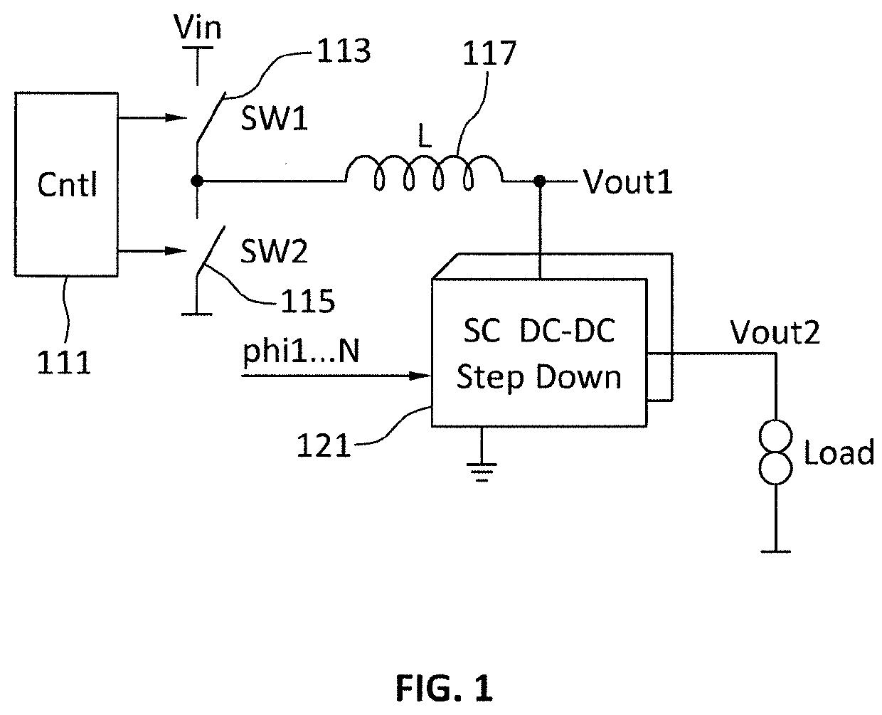
[0023]FIG. 1 is a semi-schematic, semi-block diagram including voltage regulator circuitry in accordance with aspects of the invention. As shown in FIG. 1, a pair of switches, a high side switch 113 and a low side switch 115, are coupled in series between an input voltage and a lower voltage. In many embodiments the input voltage is a supply voltage, for example provided by a battery, and in some embodiments the lower voltage is ground. A first end of an inductor 117 is coupled to a node between the high side switch and the low side switch. A second end of the inductor is coupled by way of a DC-DC switched capacitor step down converter 121 to ground. An output from the DC-DC switched capacitor step down converter, which may be referred to simply as a switched capacitor converter, provides power to a load. Generally, the switched capacitor converter always includes at least one capacitor coupled between the output to the load and ground (or some other lower voltage, for example the l...


PUM


Abstract

A DC-DC switching converter with an LC output filter has a switched capacitor converter providing the capacitance of the output filter. The switched capacitor converter may be a multi-phase switched capacitor converter. Topology of connections between capacitors of the multi-phase switched capacitor converter may be dependent on phases of clock signal(s) provided to the multi-phase switched capacitor converter. The switched capacitor converter may rely on parasitic inductances, or include discrete inductors, in series between connected capacitors to allow for adiabatic or near adiabatic voltage conversion.

Description

CROSS REFERENCE TO RELATED APPLICATION[0001]This application claims the benefit of the filing date of U.S. Provisional Patent Application No. 62 / 689,613, filed on Jun. 25, 2018, the disclosure of which is incorporated by reference herein.BACKGROUND OF THE INVENTION[0002]The present invention relates generally to power management for semiconductor devices, and more particularly to use of switched capacitor converters in semiconductor power management devices.[0003]Integrated circuits generally require provision of power within particular parameters during operation. The provision of such power may face many complexities. For example, semiconductor chips including the integrated circuits may have different portions that require power at the same or different times, different portions may require power within different parameters, and some portions may utilize different amounts of power at different times. This may be particularly true for those chips integrating multiple components th...

Claims


Application Information

Patent Timeline
Patent Type & Authority Applications(United States)
IPC IPC(8): H02M3/156H02M3/06G05F1/52
CPCG05F1/52H02M3/06H02M3/156H02M3/07H02M1/0045H02M1/007
Inventor TEPLECHUK, MYKHAYLODOSLUOGLU, TANER
Owner ENDURA IP HLDG LTD
Why Eureka
Try Eureka