
Nonreciprocal circuit device including two series resonant circuits having differing resonant frequencies

a circuit device and non-reciprocal technology, applied in waveguide devices, basic electric elements, electrical equipment, etc., to achieve the effect of increasing costs

Inactive Publication Date: 2005-03-01
MURATA MFG CO LTD
View PDF20 Cites 2 Cited by
  • Summary
  • Abstract
  • Description
  • Claims
  • Application Information

AI Technical Summary

Benefits of technology

Accordingly, it is an object of the present invention to provide a small nonreciprocal circuit device wherein great amount of attenuation can be obtained at a particular frequency band, without increasing costs, and to provide a communication device using this nonreciprocal circuit device.
Generally, resonant circuits can be reduced in size as the resonance frequency becomes higher, so the configuration of the present invention wherein resonating with spurious components of frequencies higher than the center frequency and selectively attenuating them allows the circuit size to be reduced as compared with conventional nonreciprocal circuit devices such as shown in FIGS. 10 through 12 for resonating with and selectively passing the center frequency on the signal lines.
As described above, the resonance frequencies of the series resonant circuits have been set higher than the basic wave frequency, so the inductor can be miniaturized, and sufficient inductance can be obtained by extending the port portion of central conductors and bending it or suitably working the central conductors, even without adding extra components such as solenoid conductors, for example. Accordingly, the number of component parts of the nonreciprocal circuit device can be reduced, so the manufacturing process can be simplified and costs can be reduced.
The resonance frequencies of the series resonant circuits are set to be higher than the center frequency, thus forming capacitive impedance to the center frequency. By designing the inductors and capacitors of the series resonant circuits appropriately, the equivalent capacitance of the series resonant circuits is set as the equivalent matching capacitance to the center frequency. Thus, there is no need to provide other matching capacitors even in the event that series resonant circuits are provided as trap filters, thereby suppressing increasing in the number of parts, and contributing to reduction in costs.

Problems solved by technology

The primary problematic spurious component with communication devices is that with a frequency higher than the basic wave frequency.

Method used


Image

  • Nonreciprocal circuit device including two series resonant circuits having differing resonant frequencies
  • Nonreciprocal circuit device including two series resonant circuits having differing resonant frequencies
  • Nonreciprocal circuit device including two series resonant circuits having differing resonant frequencies

Examples


Embodiment Construction

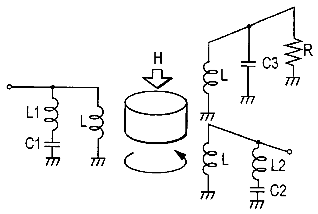
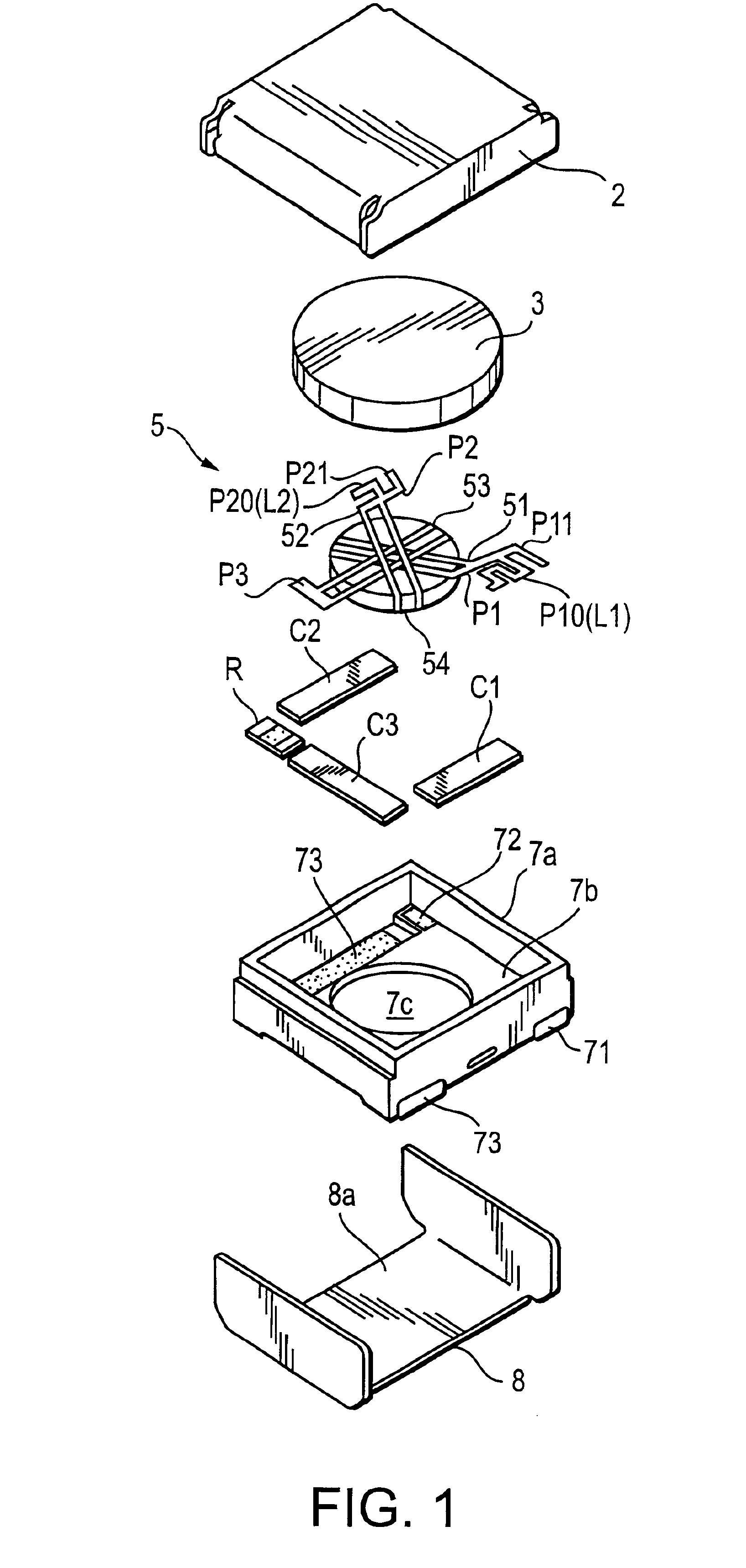
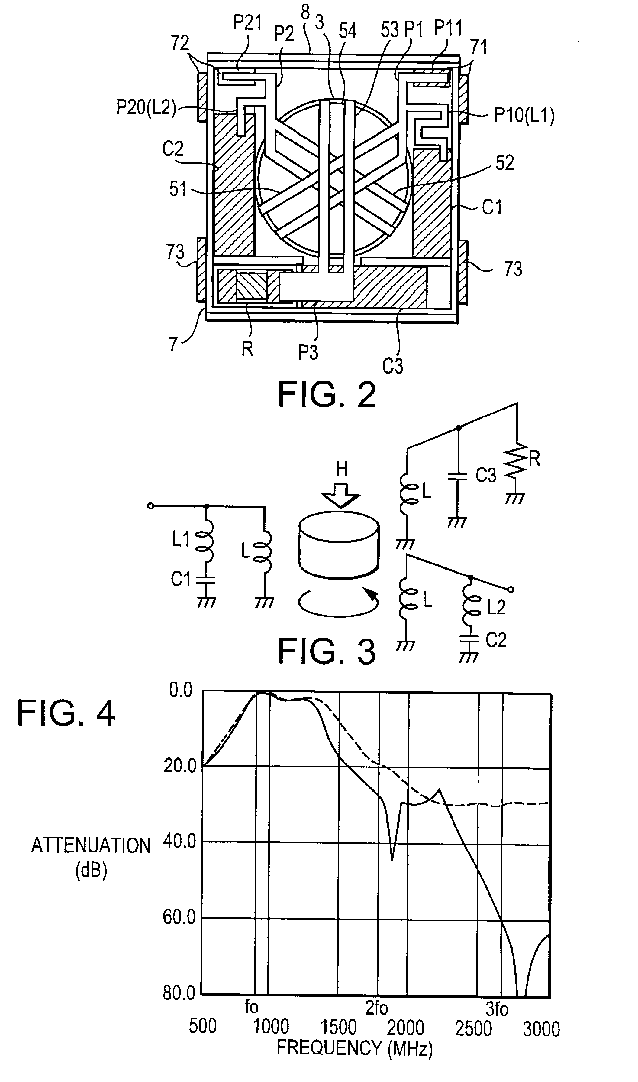
The configuration of an isolator according to an embodiment of the present invention will be described, with reference to FIGS. 1 through 3.

FIG. 1 is an exploded perspective view of an isolator, FIG. 2 is a plan view thereof with the upper yoke removed. As can be understood from FIGS. 1 and 2, this isolator has a disc-shaped permanent magnet 3 arranged on the inner side of a box-shaped upper yoke 2 made of a magnetic metal, and a magnetic closed circuit is constituted by the upper yoke 2 and a lower yoke 8 which is also made of a magnetic metal and has an approximate shape of a box with one end opened, a resin case 7 is provided on the bottom surface 8a inside of the lower yoke 8, and a magnetic assembly 5, matching capacitors C1, C2, and C3 and a terminal resistor R are arranged within the resin case 7.

The above magnetic assembly 5 has the following configuration. Three central conductors 51, 52, and 53 have a shared ground portion. The bottom surface of a rectangle-shaped plate fe...


PUM


Abstract

Three mutually intersecting central conductors are positioned on ferrite to which a direct current magnetic field is applied, the port portions of two of the central conductors are branched and one branched portion of each is extended and bent so as to form an inductor. These inductors and capacitors with one end connected to a ground terminal make up series resonant circuits. The resonance frequencies of the series resonant circuits are set to approximately two times and approximately three times that of the center frequency of the pass band of the device which is the fundamental frequency, thereby causing attenuation of the second harmonic frequency and third harmonic frequency of the fundamental frequency, thus acting as matching capacitance of the fundamental frequency. Accordingly, a small nonreciprocal circuit device having a great amount of attenuation of a particular frequency is obtained without increasing costs, a nonreciprocal circuit device, and a communication device using the same, are provided.

Description

BACKGROUND OF THE INVENTION1. Field of the InventionThe present invention relates to a nonreciprocal circuit device, such as an isolator or circulator or the like used at high-frequency bands such as microwave bands, and to a communication device using the nonreciprocal circuit device.2. Description of the Related ArtConventionally, nonreciprocal circuit devices such as lumped parameter isolators and circulators have been widely used for communication devices and the like for ensuring stable operations and protection of oscillators and amplifiers, employing the properties thereof that the amount of attenuation in the sending direction of signals is extremely small and the amount of attenuation in the opposite direction is extremely great.A exploded perspective view of a conventional isolator is illustrated in FIG. 7 and the internal structure thereof in FIG. 8. FIG. 9 illustrates an equivalent circuit.As shown in FIGS. 7 and 8, the lumped constant isolator is arranged, within a magn...

Claims


Application Information

Patent Timeline
IPC IPC(8): H01P1/387H01P1/32H01P1/36H01P1/383
CPCH01P1/387
Inventor HASEGAWA, TAKASHI
Owner MURATA MFG CO LTD
Learn More