
Electric motor driving device

a driving device and motor technology, applied in the direction of motor/generator/converter stopper, dynamo-electric converter control, pulse technique, etc., can solve the problems of increasing loss and electromagnetic noise in failing to achieve a sufficient effect in practice, deteriorating efficiency of the motor or the generator, etc., to achieve sufficient inductance and reduce iron loss and electromagnetic noise

Inactive Publication Date: 2015-11-19
MITSUBISHI ELECTRIC CORP
View PDF2 Cites 2 Cited by
  • Summary
  • Abstract
  • Description
  • Claims
  • Application Information

AI Technical Summary

Benefits of technology

The invention is an electric motor driving device that aims to reduce iron loss and electromagnetic noise in the motor. The device achieves this by securing sufficient inductance in a carrier frequency region being used. This reduces the current ripple flowing to the motor, which in turn decreases the iron loss and electromagnetic noise. In addition, by coupleing the cores of reactors connected to the three-phase AC electric motor, the device can be made smaller.

Problems solved by technology

When this current ripple is large, an iron loss and an electromagnetic noise in the motor or the generator are increased and efficiency of the motor or the generator is deteriorated.
This proposal, however, fails to achieve a sufficient effect in practice.
A cause of this failure in fully reducing an iron loss and an electromagnetic noise is found in characteristics of an iron material and a magnetic steel sheet material used as a core material of the motor or the generator.
However, magnetic permeability of the iron material and the magnetic steel sheet material used as the core material of the motor or the generator has a frequency dependency, and this frequency dependent characteristic considerably affects the inductance.
Consequently, there arises a problem that a current ripple becomes larger and hence an iron loss and an electromagnetic noise in the motor or the generator are increased.

Method used


Image

  • Electric motor driving device
  • Electric motor driving device
  • Electric motor driving device

Examples


first embodiment

[0025]Hereinafter, an electric motor driving device of the invention will be described according to the drawings.

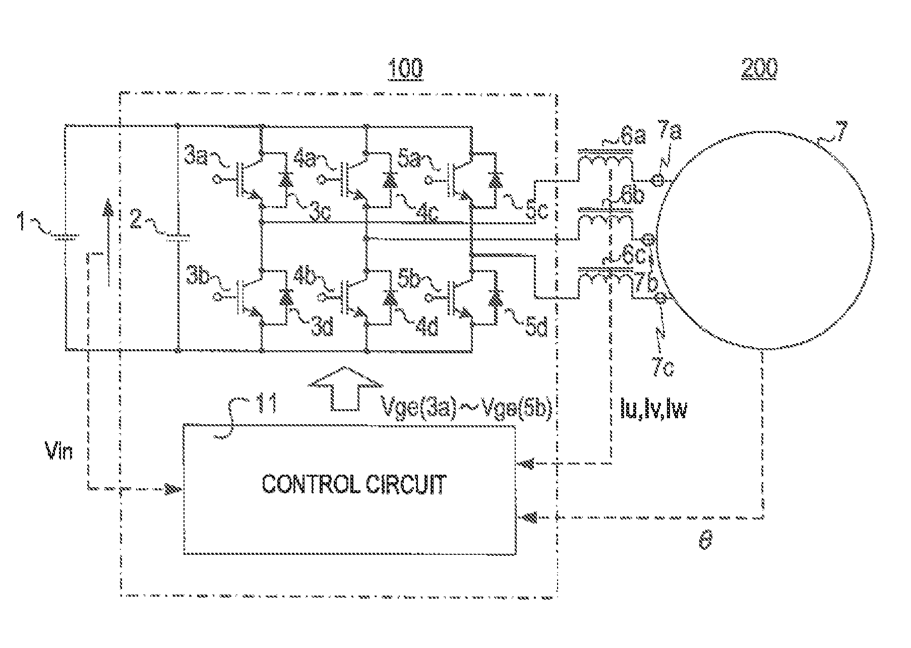
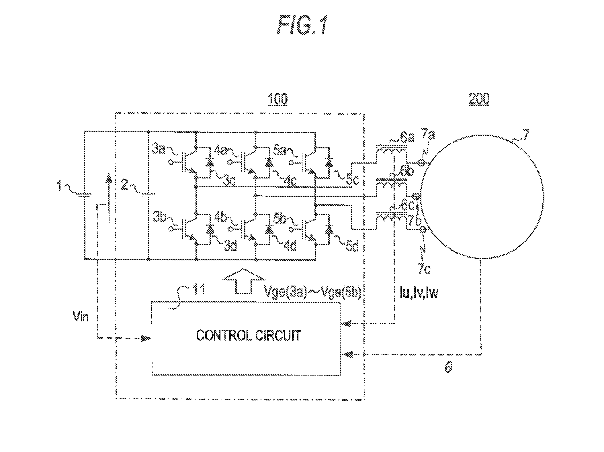
[0026]FIG. 1 is a view showing a configuration of an electric motor driving device according to a first embodiment of the invention. As is shown in the drawing, in an electric motor driving device 200, an energy storage device 1, an inverter device 100, and an electric motor 7 are connected in series, and reactors 6a, 6b, and 6c are connected between the electric motor 7 and the inverter device 100 in series, respectively, to AC terminals 7a, 7b, and 7c of respective phases of the electric motor 7.

[0027]The inverter device 100 is formed of a smoothing capacitor 2, an IGBT (Insulated Gate Bipolar Transistor) 3a through an IGBT 5b, a diode 3c through a diode 5d, and a control circuit 11. The electric motor driving device 200 includes the energy storage device 1, the inverter device 100, the reactors 6a through 6c, and the electric motor 7.

[0028]A lithium-ion battery, a nick...

second embodiment

[0040]Hereinafter, an electric motor driving device according to a second embodiment of the invention will be described using FIG. 4.

[0041]A circuit configuration of the electric motor driving device according to the second embodiment of the invention is basically the same as the one described in the first embodiment above and a description of the same portions is not repeated herein. A difference is that cores of reactors 6a through 6c capable of maintaining inductance even in a carrier frequency region are coupled to one another. The number of reactors can be reduced as a result.

[0042]A circuit operation of the electric motor driving device 200 according to the second embodiment of the invention is the same as the one described in the first embodiment above.

[0043]In addition to the effects of the electric motor driving device of the first embodiment above, the electric motor driving device according to the second embodiment of the invention can satisfy a need of a size reduction.

[...

third embodiment

[0045]Hereinafter, an electric motor driving device 200 according to a third embodiment of the invention will be described using FIG. 5.

[0046]A circuit configuration of the electric motor driving device according to the third embodiment of the invention is basically the same as the one described in the first embodiment above and a description of the same portions is not repeated herein. A difference is that a reactor core 8 with a characteristic to maintain inductance even in a carrier frequency region is used as a core material of an electric motor 7. Accordingly, the reactor 6a through the reactor 6c can be replaced by the reactor core 8 and a need of a further size reduction can be satisfied.

[0047]A circuit operation of the electric motor driving device 200 according to the third embodiment of the invention is the same as the one described in the first embodiment above.

[0048]The electric motor driving device 200 according to the third embodiment of the invention can obtain effect...


PUM


Abstract

A decrease of inductance in a carrier frequency region being used is suppressed by connecting reactors capable of maintaining a fluctuation range of inductance within a predetermined range in the carrier frequency region in series to and between an inverter device converting electric power of an energy storage device and an electric motor. Consequently, the electric motor is controlled while an iron loss and an electromagnetic noise are reduced independently of characteristics of an iron material and a magnetic steel sheet material used as a core material of the electric motor.

Description

BACKGROUND OF THE INVENTION[0001]1. Field of the Invention[0002]The present invention relates to an electric motor driving device that supplies an electric motor with electric power from an energy storage device by controlling charging and discharging of the energy storage device or supplies the energy storage device with regenerative electric energy of the electric motor.[0003]2. Description of the Related Art[0004]A need for a gasoline car to improve fuel efficiency is increasing these days and attention is being paid to cars using electric energy as a technique achieving improvement of fuel efficiency. In particular, an eco-friendly car incorporating an energy storage device (lithium-ion battery, nickel-metal hydride battery, or the like), such as a hybrid car and a plug-in hybrid car, is becoming popular. Such a hybrid car combines an existing gasoline car and a system that obtains running motive power by converting a DC power supply supplied from the energy storage device to an...

Claims


Application Information

Patent Timeline
Patent Type & Authority Applications(United States)
IPC IPC(8): H02P6/00
CPCH02P6/002H02P27/08H02P6/28
Inventor FUJITA, MASAHIKOTAKESHIMA, YOSHIHIROYAMADA, MASAKI
Owner MITSUBISHI ELECTRIC CORP
Learn More