

Embedded inductor and manufacturing method thereof
a manufacturing method and inductor technology, applied in the field of embedded inductor, can solve the problems of cracks, inductance and dc bias of the inductor, and the like, and achieve the effects of reducing the manufacturing process, and reducing the manufacturing cos
- Summary
- Abstract
- Description
- Claims
- Application Information
AI Technical Summary
Benefits of technology
Problems solved by technology
Method used
Image

Examples
Embodiment Construction
Cross Reference to Related Applications
[0001] This Non-provisional application claims priority under 35U.S.C. §119(a) on Patent Application No(s). 094143295 filed in Taiwan, Republic of China on Dec. 8, 2005, the entire contents of which are hereby incorporated by reference.
BACKGROUND OF THE INVENTION
[0002] 1. Field of Invention
[0003] The invention relates to an inductor and a manufacturing method thereof. In particular, the invention relates to an embedded inductor and the manufacturing method thereof.
[0004] 2. Related Art
[0005] As the electronic products become smaller, the sizes of basic and important components such as inductors also have to be shrunk in proportion.
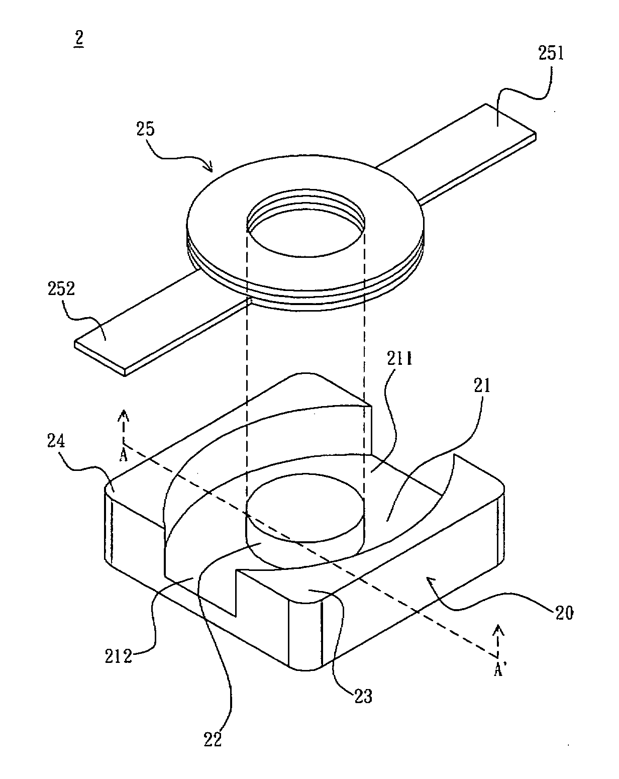
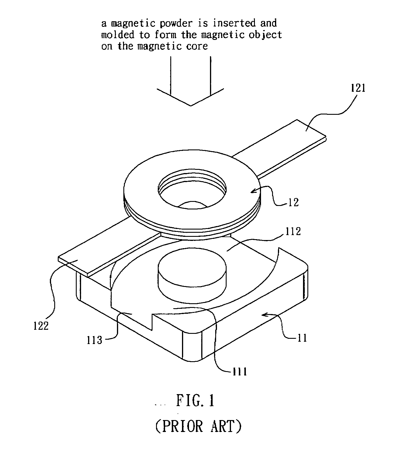
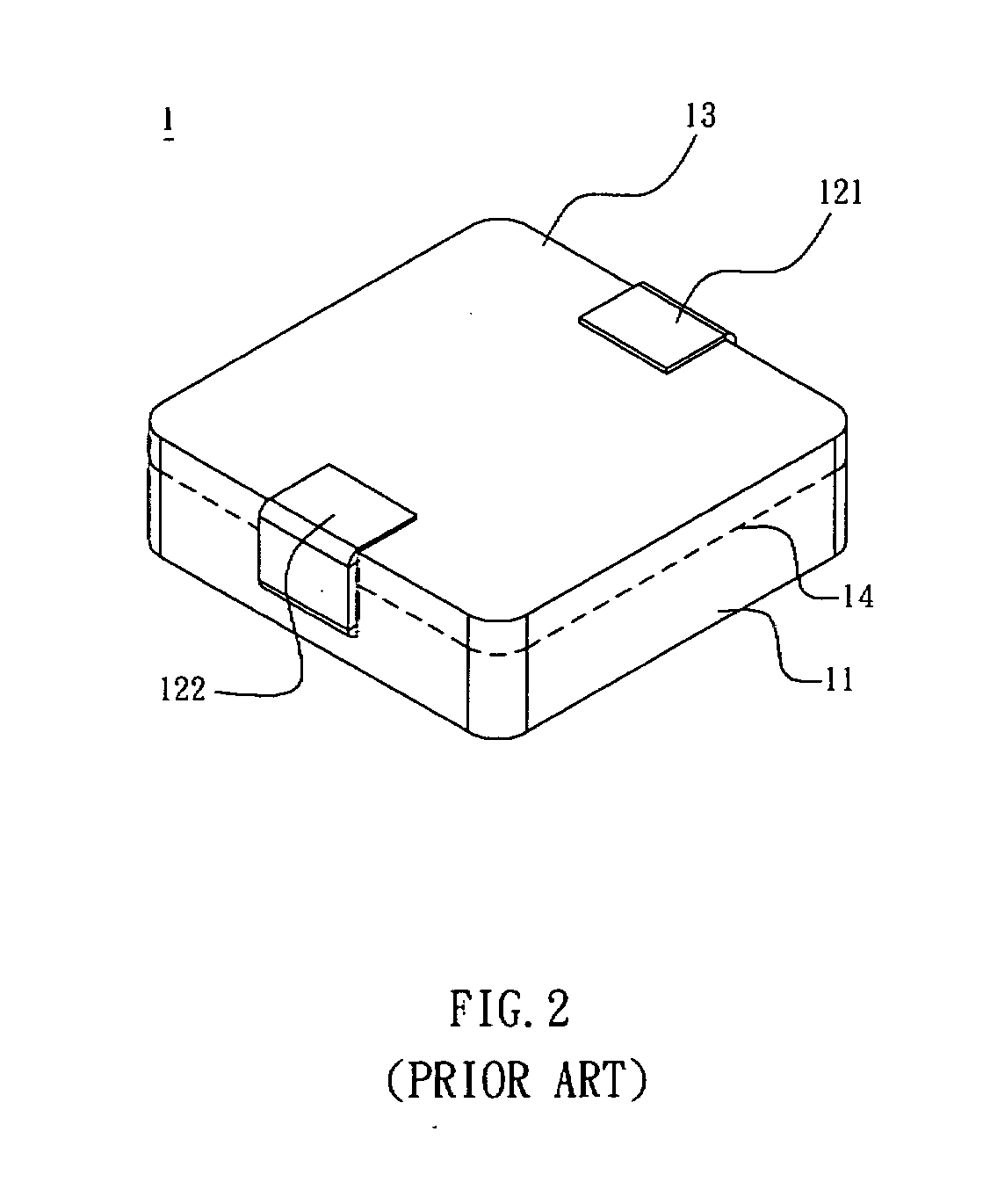
[0006] As shown in FIGS. 1 and 2, a conventional embedded inductor 1 includes a pre-formed magnetic core 11, a coil 12, and a magnetic object 13. The magnetic core 11 has one recession 111 and two openings 112, 113. The coil 12 is then disposed in the recession 111. The coil 12 has a first end 121 and a second ...
PUM
| Property | Measurement | Unit |
|---|---|---|
| height | aaaaa | aaaaa |
| height | aaaaa | aaaaa |
| density | aaaaa | aaaaa |
Abstract
Description
Claims
Application Information