Catheter system for continuous irrigation

a catheter system and continuous technology, applied in the field of catheters, can solve the problems of insufficient effect, large cumulative burden of cautis on patients and hospitals, and resistance of biofilms to antibiotics/antimicrobials, and achieve the effect of magnifying the effect of glands

Pending Publication Date: 2020-01-02
CIC FUND SECURITISATION SA
View PDF11 Cites 10 Cited by
  • Summary
  • Abstract
  • Description
  • Claims
  • Application Information

AI Technical Summary

Benefits of technology

[0009]It is therefore one object of the present invention to provide an indwelling urinary catheter system having (1) an elongated tubular catheter body having a distal end and a proximal end; (2) at least one sleeve portion constructed substantially out of a semipermeable membranes surrounding at least one portion of the catheter body; (3) at least one lumen to instill fluid into the catheter body; and (4) a means to continuously efflux the instilled fluid through the semipermeable membrane of at least one sleeve resulting in the circumferential egress of fluid out of the semipermeable membrane around the catheter body. The catheter may further include a drainage lumen extending through the catheter body from just short of the distal end to the proximal end and an opening or eyelet in the catheter body just short of the distal end of the catheter body to permit urine to drain from a patient's bladder into the drainage lumen. The catheter body is disposed within the urethra of the patient and a retaining mechanism, such as an inflatable balloon, is disposed within the patient's bladder to retain the catheter in position. The fluid instilled into the catheter body and effluxed from the sleeve portion(s) may include, but is not limited to, antiseptics, antibiotics or antimicrobials, and / or combinations thereof to prevent biofilm formation on the exterior surface of the catheter body. The fluid may also include certain therapeutic agents used in intravesical therapy, such as immunotherapy agents or chemotherapeutic agents. The fluid may also include agents for patient comfort, such as antispasmodics and pain medicines. All such agents can be effluxed directly into the bladder through the semipermeable sleeve portion around the catheter tip placed within the bladder.

Problems solved by technology

While morbidity that is attributable to a single episode of catheterization is limited, the high frequency of catheter use (around 25% of hospitalized patients) means that the cumulative burden of CAUTIs on patients and hospitals is substantial.2 1 D.
Biofilms are resistant to antibiotics / antimicrobials due to the fact that these agents cannot penetrate sufficiently through the exopolysaccharide layer.
This is not surprising, as while a variety of approaches for prevention of biofilm formation include the use of biocoatings, impregnating materials with antibiotics, antimicrobials or other materials as well as catheters capable of eluting antibiotics and / or antimicrobials have been used, none have been fully effective.
Further, one of the major complications associated with antibiotic based coatings is the development of resistance.
When used in clinical studies, the uncontrolled release profiles of the drugs resulted in the elution of initial high local concentrations that may initially damage the cells followed by concentrations that are not inhibitory.4 By not killing all of the bacteria effectively, any subsequent infection will be more difficult to eradicate due to the development of resistance.
The drug is slowly and continuously released into the bladder or along urethra; however, there is no continual washing of the periurethral space, where bacteria adhere, form biofilms and result in bacterial infections.

Method used


Image

  • Catheter system for continuous irrigation
  • Catheter system for continuous irrigation
  • Catheter system for continuous irrigation

Examples


Embodiment Construction

[0035]For the purposes of the present invention, the term “semipermeable” is intended to encompass not only those materials that are semipermeable by their nature (i.e. those that allow certain substances to pass through it while not allowing other materials to pass through it) but materials that may be made semipermeable by creating pores of a predetermined size that would allow certain substances to pass through it while not allowing other materials to pass through it.

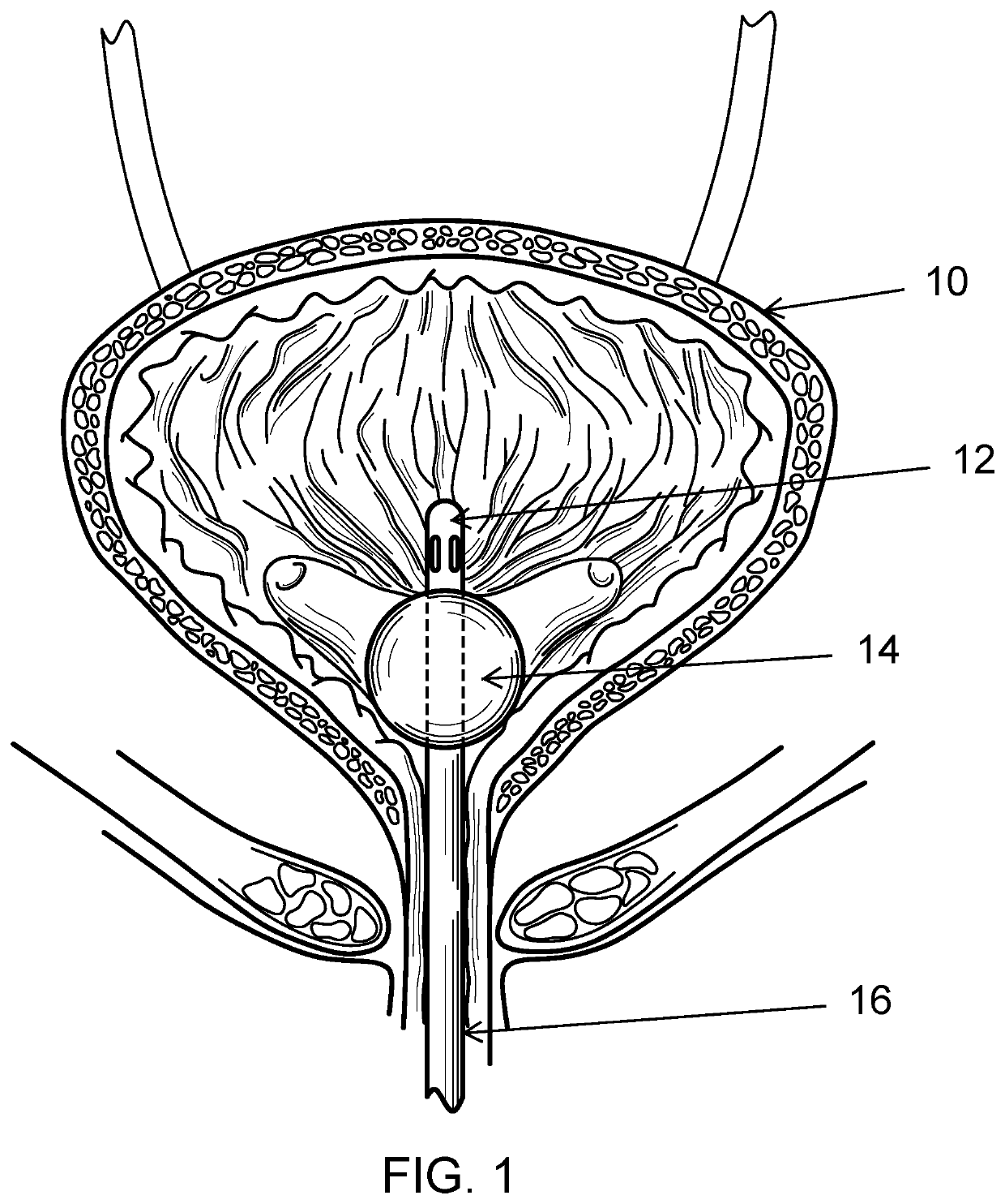
[0036]Turning to the drawings, there shown in FIG. 1 is a traditional catheter for insertion into a cavity, duct, or a vessel to permit injection or withdrawal of fluids into or from the cavity, duct, or vessel, or to establish patency of a passageway. For example, the catheter body 16 may be inserted through a patient's urethra and into the patient's bladder 10 for draining urine from the bladder and / or instilling fluid into the bladder through slots in the tip 12 of the catheter. A retaining device, such as the bal...


PUM


Abstract

An indwelling urinary catheter system having an elongated tubular catheter body 401 having a distal end and a proximal end; at least one sleeve portion 406 constructed out of a semi-permeable membranes surrounding at least one portion of the catheter body; at least one lumen to instill fluid into the catheter body; and a means to continuously efflux the instilled fluid through the semi-permeable membrane for circumferential egress of fluid out of the membrane around the catheter body. The catheter may further include a drainage lumen 414 extending through the catheter body from just short of the distal end to the proximal end and an opening or eyelet 405 in the catheter body just short of the distal end of the catheter body to permit urine to drain from a patient's bladder into the drainage lumen. A retaining mechanism may also be comprised.

Description

RELATED APPLICATIONS[0001]This application claims priority to U.S. Provisional Application No. 62 / 454,829 filed Feb. 5, 2017. The entire contents of the above application are hereby incorporated by reference as though fully set forth herein.FIELD[0002]The present invention pertains to a catheter, and more particularly, to intra-urethral or indwelling catheters capable of effluxing fluids.BACKGROUND[0003]The traditional Foley-type catheter is well known in the art and comprises an inflatable balloon disposed within the patient's bladder and a discharge tube extending through the urethra to the exterior. The Foley-type catheter provides passive urinary drainage, and the ability to clamp the catheter closed at a location exterior of the patient.[0004]Urethral catheters, such as Foley-catheters, are used to drain urine from the bladder. A urinary tract infection (also called “UTI”) is an infection in the urinary system, which includes the bladder and kidneys. When a urinary catheter is ...

Claims


Application Information

Patent Timeline
Patent Type & Authority Applications(United States)
IPC IPC(8): A61M25/00A61M39/10
CPCA61M39/105A61M2025/0056A61M2210/1085A61M25/0017A61M2025/0057A61M25/0041A61M25/0026A61M2210/1089A61M25/04A61M3/0283A61M2025/0019A61M2205/3331B01D2325/0283
Inventor MCINTYRE, MATTHEW G.
Owner CIC FUND SECURITISATION SA
Why Eureka
Try Eureka