
Method for installing filler tube and installation structure for filler tube

a technology of filler tube and installation structure, which is applied in the direction of liquid fuel feeders, machines/engines, vehicle sub-unit features, etc., can solve the problem of requiring more costs as a factor

Inactive Publication Date: 2020-01-02
SUMITOMO RIKO CO LTD
View PDF0 Cites 0 Cited by
  • Summary
  • Abstract
  • Description
  • Claims
  • Application Information

AI Technical Summary

Benefits of technology

The patent text discusses a method for securely welding the fuel tank and filler tube together. The technical effect of the invention is to reduce the time and cost associated with warming the welding sites and actually welding them together. This is achieved by using a facing space between the front-side peripheral face of the fuel tank and the tube flange of the filler tube, which allows for quicker movement and evacuation of the heat plate. Additionally, the absence of any other member in the facing space eliminates the need for control of interspaces, reducing manufacturing costs. Furthermore, the filler tube does not require a highly accurate mold, further reducing manufacturing costs.

Problems solved by technology

However, the intervening member, which sits astride the opening of the fuel tank to extend toward the both sides of the opening, has prolonged the distance over which the fuel tank and filler tube move for the evacuation of the heat plate from the facing space.
This makes a factor of requiring more costs.

Method used


Image

  • Method for installing filler tube and installation structure for filler tube
  • Method for installing filler tube and installation structure for filler tube
  • Method for installing filler tube and installation structure for filler tube

Examples


Embodiment Construction

1. Construction of Fuel Line 1

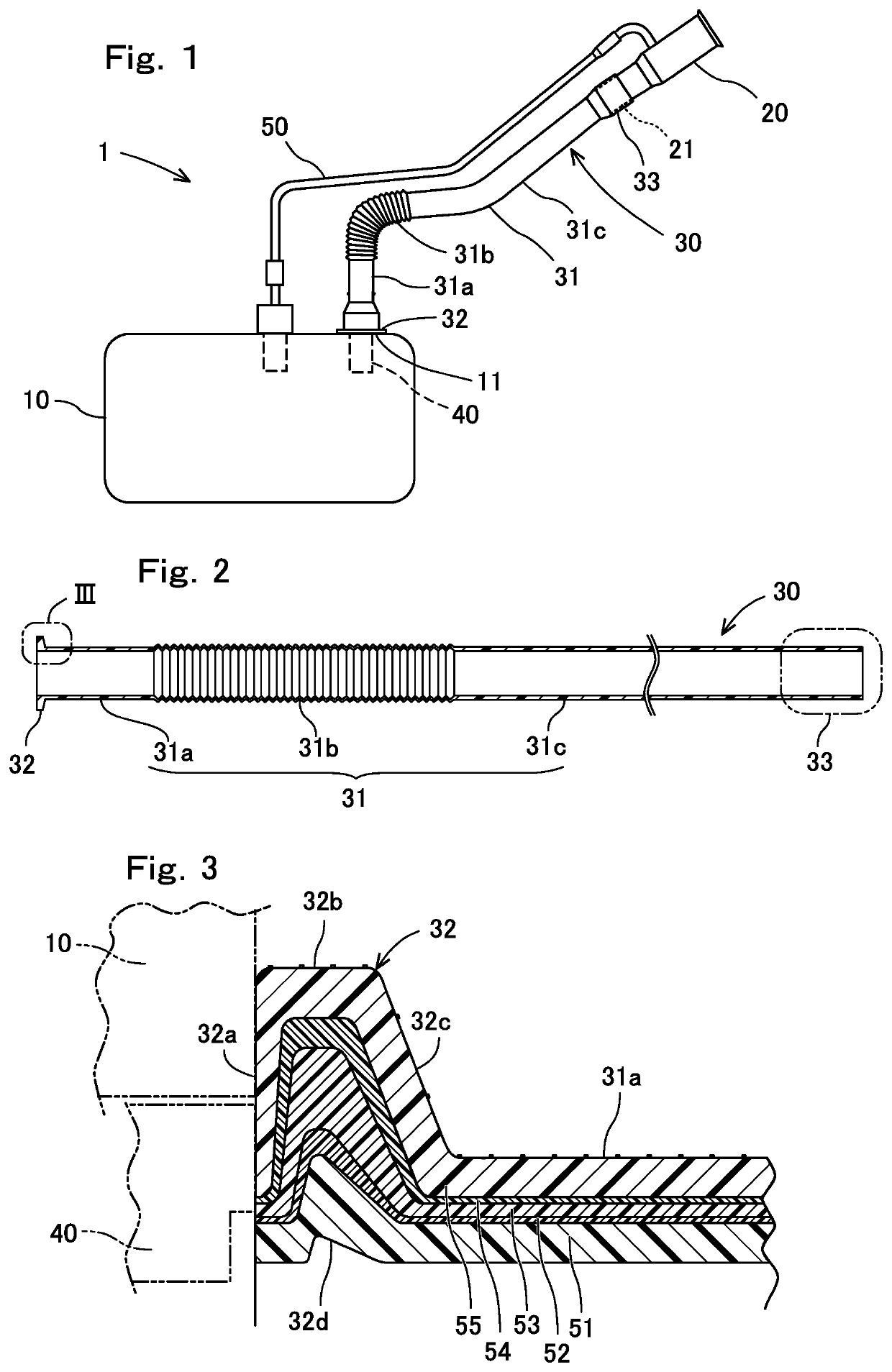
[0038]How a fuel line 1 is constructed will be hereinafter described with reference to FIG. 1. The fuel line 1 makes a line from a filler neck and up to an internal combustion engine (not shown) in an automobile. In the present embodiment, however, the fuel line 1 will be hereinafter described while focusing on the part from a filler neck 20 but up to a fuel tank 10.

[0039]As illustrated in FIG. 1, the fuel line 1 comprises the fuel tank 10, the filler neck 20, a filler tube 30, an intervening member 40, and a breather line 50. The fuel tank 10, which is molded with thermoplastic resin, reserves a liquid fuel, such as gasoline, in it. The liquid fuel reserved in the fuel tank 10 is supplied to the not-shown internal combustion engine, and is used to drive it. The fuel tank 10 is provided with an opening 11 for supplying fuel. The opening 11 is formed in the top face or side of the fuel tank 10. The filler neck 20 is disposed at around an automobile outer...


PUM

PropertyMeasurementUnit
structureaaaaaaaaaa
fitting forceaaaaaaaaaa
cylindrical shapeaaaaaaaaaa

Abstract

A method for installing filler tube includes the steps of: preparing a fuel tank including an opening; preparing an intervening member including a cylindrical member body and an annular member flange; preparing a filler tube including a cylindrical tube body and an annular tube flange; arranging the intervening member so that not only the member body is arranged in the interior of the fuel tank through the opening but also the member flange locks to a front-side peripheral face of the opening of the fuel tank; and welding not only the front-side peripheral with the tube flange but also the member flange with the tube flange by arranging a hot plate in a facing space between the front-side peripheral face and the tube flange and then warming the front-side peripheral face, the member flange and the tube flange.

Description

CROSS REFERENCE TO RELATED APPLICATIONS[0001]The present application is a Continuation application of International Application No. PCT / JP2019 / 003614, filed on Feb. 1, 2019, which is incorporated herein by reference. The present invention is based on Japanese Patent Application No. 2018-042465, filed on Mar. 9, 2018, the entire contents of which are incorporated herein by reference.BACKGROUND OF THE INVENTION1. Field of the Invention[0002]The present invention relates to a method for installing filler tube, and an installation structure for filler tube.2. Description of the Related Art[0003]JP5797690B2, and JP2003-194280A disclose to weld a flange, which is disposed at one of the axial opposite ends of a filler tube, onto a front-side peripheral face of an opening of a fuel tank. Moreover, JP5797690B2 discloses to arrange an intervening member (e.g., an inlet check valve, or the like) in the opening of the fuel tank. The intervening member sits astride the opening of the fuel tank, ...

Claims


Application Information

Patent Timeline
Patent Type & Authority Applications(United States)
IPC IPC(8): B29C65/20B29C48/00B29C48/09B29C65/00
CPCB29C48/0019B29C48/09B29C66/5344B29K2101/12B29L2031/7172B29K2701/12B29C65/20B60K15/04F16L47/02F02M37/00B60K15/03B60K2015/03032B60K2015/03046B60K15/03177B60Y2410/124B60K2015/0346B29C65/2061B29C66/1312B29C66/131B29C66/112B29C66/53247B29C66/73921B29C66/543B29C66/61B29C66/7234B29C66/71B29C48/303B29K2023/065B29K2077/00B29K2023/086
Inventor JIANG, LINTSUKADA, HARUKI
Owner SUMITOMO RIKO CO LTD
Learn More