
Temperature-controlled flange and reactor system including same

a temperature control and reactor technology, applied in the field of flanges, can solve problems such as gas leakage, deterioration, and material formation that can generate particles on the substrate during processing, and achieve the effect of reducing the degradation of the seal and reducing the condensation of precursors

Active Publication Date: 2020-01-02
ASM IP HLDG BV
View PDF1 Cites 239 Cited by
  • Summary
  • Abstract
  • Description
  • Claims
  • Application Information

AI Technical Summary

Benefits of technology

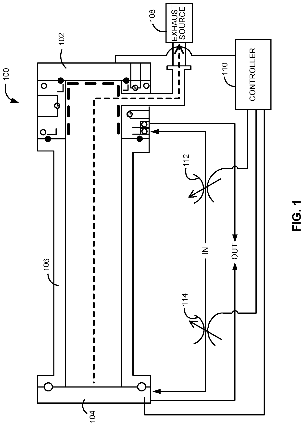
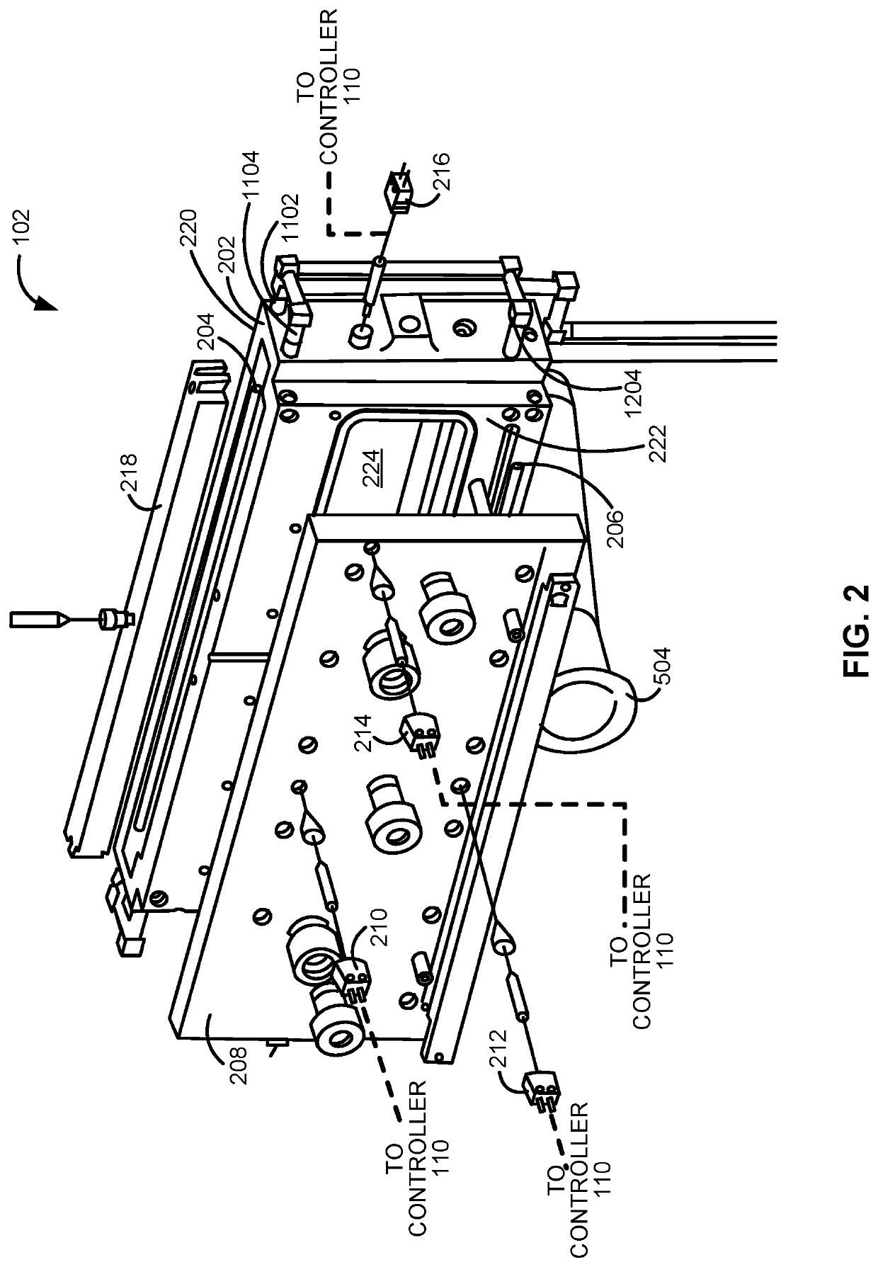
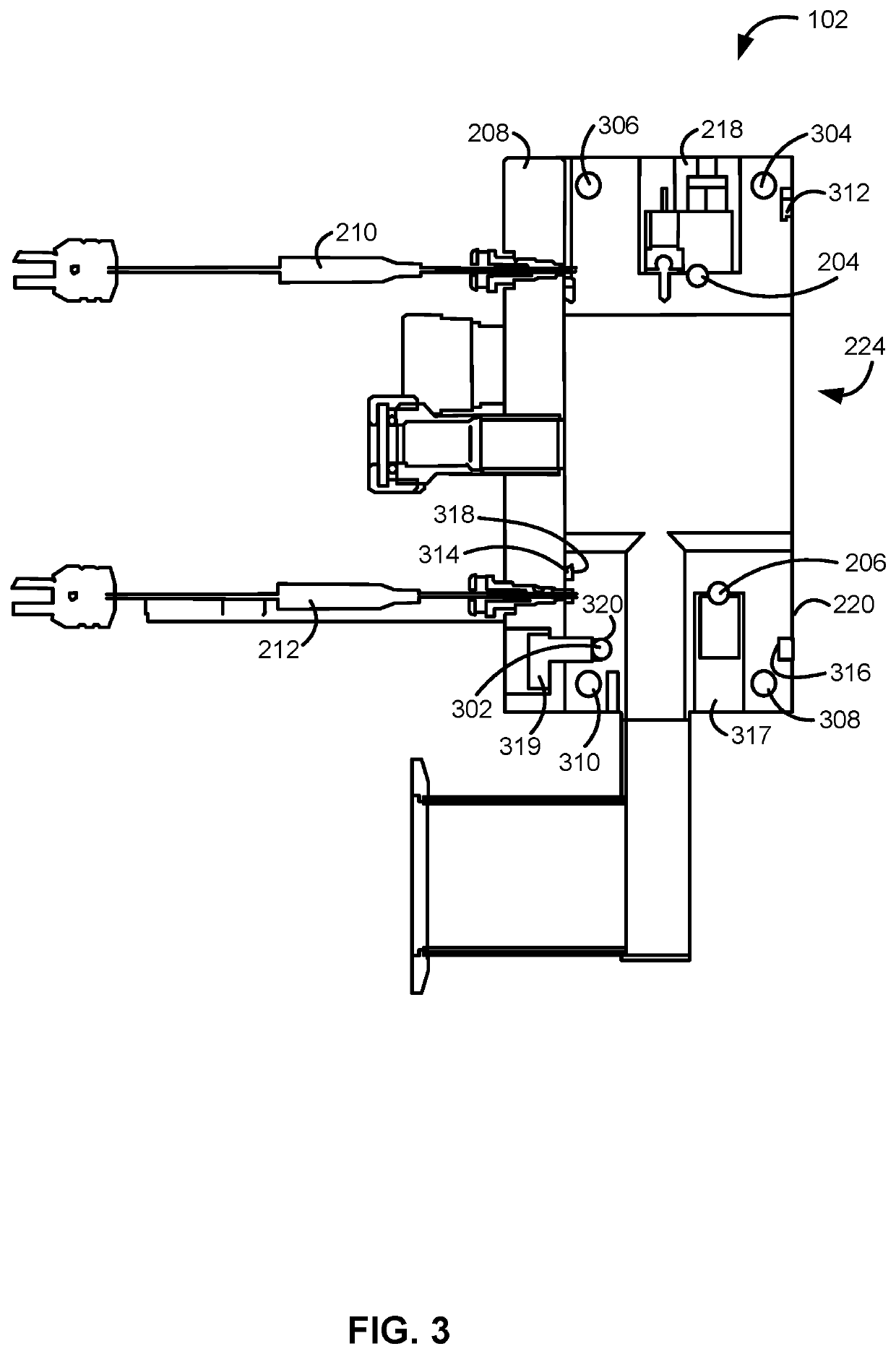
The present invention relates to flanges, flange assemblies, and reactor systems including them. The invention provides flanges with heatable and coolable sections that can mitigate degradation of the seal and prevent condensation of precursors and byproducts on the flange. The flanges can be attached to the front or back end of the reaction chamber and can have a recess for a sealing member. The cooling channel can be placed near the recess to prevent the sealing member from reaching undesirable temperatures during substrate processing. Overall, the invention improves the performance and durability of flanges in chemical reactions.

Problems solved by technology

For example, gas-phase reactors can often operate at temperatures of up to 200° C. However, such elevated temperature may deleteriously affect (e.g., cause deterioration of) the resilient seal used to couple the first or second flange to the reaction chamber and / or other reactor system components.
Such deterioration can result in gas leakage.
However, if the temperature of the flange is intentionally reduced, relative to the operating temperature of the reaction chamber during substrate processing to protect the resilient seal, the precursors and / or reaction byproducts can react with and / or condense onto a surface of the flange, creating materials that can generate particles on the substrates during processing and / or that may be hazardous.
This problem may become even more pronounced when using precursors that originate as a liquid or solid.

Method used


Image

  • Temperature-controlled flange and reactor system including same
  • Temperature-controlled flange and reactor system including same
  • Temperature-controlled flange and reactor system including same

Examples


Embodiment Construction

[0023]The description of exemplary embodiments provided below is merely exemplary and is intended for purposes of illustration only; the following description is not intended to limit the scope of the disclosure or the claims. Moreover, recitation of multiple embodiments having stated features is not intended to exclude other embodiments having additional features or other embodiments incorporating different combinations of the stated features.

[0024]The present disclosure generally relates to flanges and flange assemblies suitable for coupling to a reaction chamber, to reactor systems including the flange(s) and / or flange assemblies, and to methods of using the flanges, flange assemblies, and reactor systems.

[0025]The reactor systems including a one or more flanges and / or flange assemblies as described herein can be used to process substrates, such as semiconductor wafers, in gas-phase reactors. By way of examples, the systems described herein can be used to form or grow epitaxial l...


PUM

PropertyMeasurementUnit
temperatureaaaaaaaaaa
temperaturesaaaaaaaaaa

Abstract

A flange, flange assembly, and reactor system including the flange and flange assembly are disclosed. An exemplary flange assembly includes heated and cooled sections to independently control temperatures of sections of the flange. Methods of using the flange, flange assembly and reactor system are also disclosed.

Description

FIELD OF DISCLOSURE[0001]The present disclosure generally relates to gas-phase reactors and systems. More particularly, the disclosure relates to flanges for gas-phase reactors, to reactor systems including one or more of the flanges, and to methods of using the same.BACKGROUND OF THE DISCLOSURE[0002]Gas-phase reactors, such as chemical vapor deposition (CVD), plasma-enhanced CVD (PECVD), atomic layer deposition (ALD), and the like, can be used for a variety of applications, including depositing and etching materials on a substrate surface. For example, gas-phase reactors can be used to deposit and / or etch layers on a substrate to form semiconductor devices, flat panel display devices, photovoltaic devices, microelectromechanical systems (MEMS), and the like.[0003]A typical gas-phase reactor system includes a reactor including a reaction chamber, one or more precursor gas sources fluidly coupled to the reaction chamber, one or more carrier and / or purge gas sources fluidly coupled to...

Claims


Application Information

Patent Timeline
Patent Type & Authority Applications(United States)
IPC IPC(8): C23C16/455
CPCC23C16/455B01J19/0013B01J19/0053C23C16/4409C23C16/4411C30B25/12C30B25/10C23C16/4586C23C16/4585C23C16/4412C23C14/50C23C14/541C23C14/564H01J37/32724H01J37/32834
Inventor SREERAM, SONTITOLLE, JOHNMARGETIS, JOESU, JUNWEI
Owner ASM IP HLDG BV
Learn More