Pulse combustor performance improvement with airspeed

a technology of combustors and pulsejet engines, which is applied in the direction of machines/engines, intermittent jet plants, combustion air/fuel air treatment, etc., can solve the problems of air pressure increase and airspeed decrease, and achieve the effect of improving engine performance with airspeed, enhancing power and thrust, and improving the efficiency of flight vehicles

Inactive Publication Date: 2020-01-02
NORTH AMERICAN WAVE ENGINE CORP
View PDF0 Cites 6 Cited by
  • Summary
  • Abstract
  • Description
  • Claims
  • Application Information

AI Technical Summary

Benefits of technology

[0018]The present invention is directed to systems and methods for improving the efficient operation of flight vehicles that use pulsejet engines as a primary or secondary propulsion system by improving engine performance with airspeed, while retaining the ability to cool such engines. According to the present invention, system and methods are provided to decelerate the velocity of the oncoming airstream encountered by a pulsejet engine that is used as the propulsion system for a flight vehicle so that sufficiently large amounts of atmospheric air can be ingested in the inlet pipe for sustained engine operation at low and high speeds / altitudes even though the fresh air has to be turned approximately 180° to enter the inlet pipe. The system and method of the present invention provides for the recovery of the dynamic pressure of the incoming fresh airstream to raise the static pressure around the open end of a rearward facing inlet pipe with the result being higher pressures and air density around the inlet pipe for improving the ingress of air into this pipe, thereby generating greater power and thrust for the pulsejet engine.

Problems solved by technology

Thus, according to the principles of fluid mass conservation, Bernoulli principles and the Venturi effect, the air expanding from the smaller diameter tubular section at the front of the diffuser duct to the larger diameter middle section to the even larger diameter distal end of the diffuser duct will result in an increase in air pressure and a decrease in airspeed.

Method used


Image

  • Pulse combustor performance improvement with airspeed
  • Pulse combustor performance improvement with airspeed

Examples


Embodiment Construction

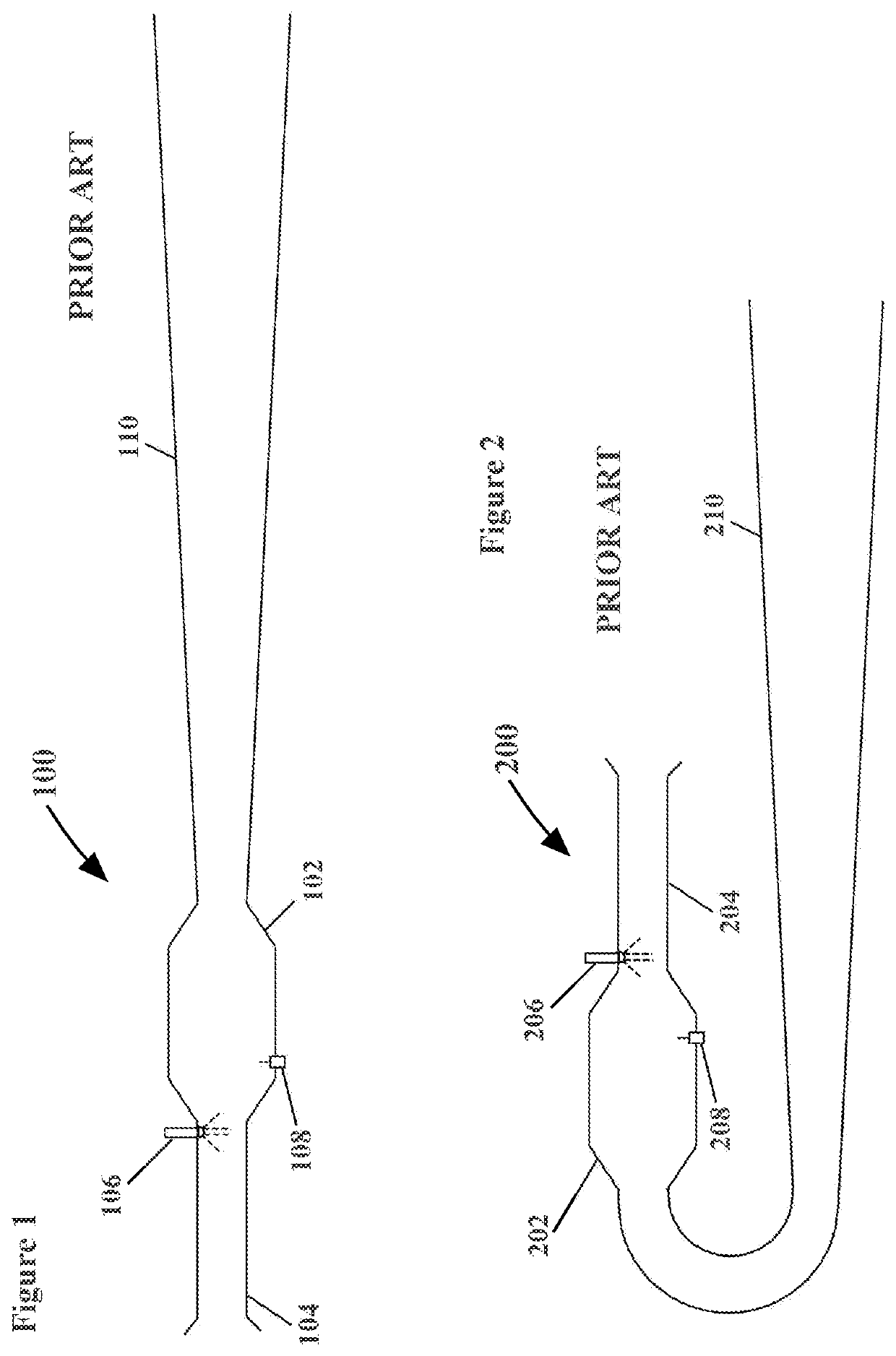
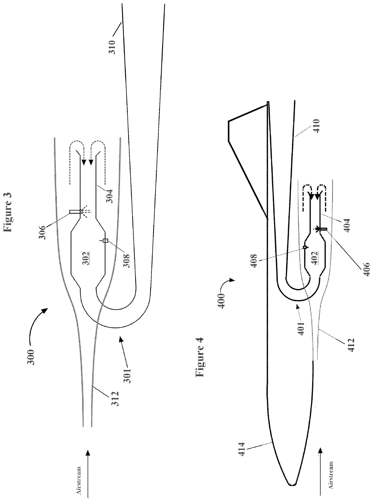
[0035]The present invention is directed to systems and methods for improving the airspeed performance of pulsejet engines and flight vehicles that incorporate pulsejet engines as a propulsion system. When a U-shaped pulsejet engine is used as the propulsion system for a flight vehicle, system and methods of the present invention are used to improve the power and thrust of the engine by decelerating the velocity of the oncoming ram airstream to which the pulsejet engine will be exposed so that the engine will be able to ingest sufficiently large amounts of atmospheric air through its rearward facing inlet pipe even though the fresh air from the airstream has to turn approximately 180° to enter the inlet pipe. The system and method of the present invention also provide for the recovery of the dynamic pressure of the incoming fresh air from the oncoming airstream to raise the static pressure around the rearward facing inlet pipe to generate higher pressure and air density around the in...


PUM


Abstract

A system and method is disclosed for improving the performance of pulsejet engines and of flight vehicles that incorporate pulsejet engines as a propulsion system. The system and method will decelerate the oncoming airstream to which a U-shaped pulsejet engine that is the propulsion system for a flight vehicle is exposed so that larger amounts of atmospheric air will be ingested into a rearward-facing inlet pipe for improved engine operation at low and high speeds/altitudes. The system and method provide for the recovery of the dynamic pressure of the incoming fresh airstream to raise the static pressure around the rearward facing inlet pipe to generate higher pressures and higher air density for improving the ingestion of air mass into the inlet pipe of the pulsejet engine thereby producing greater engine power and thrust.

Description

CROSS-REFERENCES TO RELATED APPLICATIONS[0001]This Application claims the benefit under 35 U.S.C. 119 (e) to U.S. Provisional Patent Application No. 62 / 691,393, filed Jun. 28, 2018, the entirety of which is explicitly incorporated by reference herein.[0002]All publications, patent applications, patents, or other references mentioned herein are incorporated by reference in their entirety. The patent and scientific literature referred to herein establishes knowledge that is available to those skilled in the art. The issued patents, applications, and other publications that are cited herein are hereby incorporated by reference to the same extent as if each was specifically and individually indicated to be incorporated by reference. In the case of inconsistencies, the present disclosure will prevail.FIELD OF THE INVENTION[0003]The present invention generally relates to combustors and jet engines. More specifically, the present invention relates to pulse combustors and / or pulsejet engine...

Claims


Application Information

Patent Timeline
Patent Type & Authority Applications(United States)
IPC IPC(8): F02K7/02F02C7/04F02C7/22F02C7/264F02K1/82B64D33/02
CPCF02K7/02F02C7/264F02C7/04F02C7/22B64D33/08B64D33/02B64D2033/0273F05D2220/80F02K1/822F02K1/82F02K7/067
Inventor MAQBOOL, DAANISH
Owner NORTH AMERICAN WAVE ENGINE CORP
Why Eureka
Try Eureka