Drainage catheter

Inactive Publication Date: 2020-01-16
S&G BIOTECH
View PDF0 Cites 2 Cited by
  • Summary
  • Abstract
  • Description
  • Claims
  • Application Information

AI Technical Summary

Benefits of technology

[0021]First, the first induction conduit and the second induction conduit are coupled and then, inserted together as coupled in a bile duct to allow easier installation and reduced procedure time compared with separate insertion of the first induction conduit and the second induction conduit.
[0022]Second, with a cut part formed in the second induction conduit, the first induction conduit is easily separated from the secon

Problems solved by technology

When installing a catheter in the bile ducts (40), it may be difficult to install a catheter at such branching points.
However, when stents are installed in a first branch duct and sec

Method used


Image

  • Drainage catheter
  • Drainage catheter
  • Drainage catheter

Examples


Example

[0032]Hereinafter, examples of the present invention are described in detail with reference to the accompanying drawings. However, those having ordinary skill in the pertinent technical field will easily understand that the accompanying drawings are only described in order to more easily disclose the content of the present invention and that the scope of the present invention is not limited to the scope of the accompanying drawings.

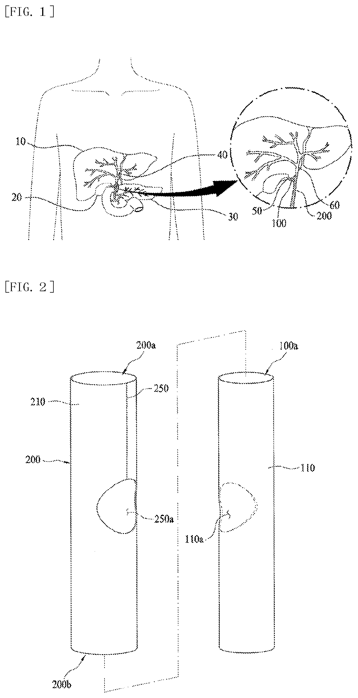
[0033]The drainage catheter according to an example of the present invention, which is installed in a bile duct (40) to broaden the bile duct (40), may be installed at a branched section of the bile duct (40).

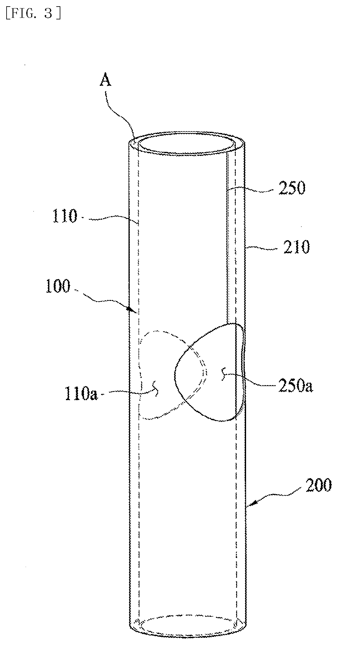
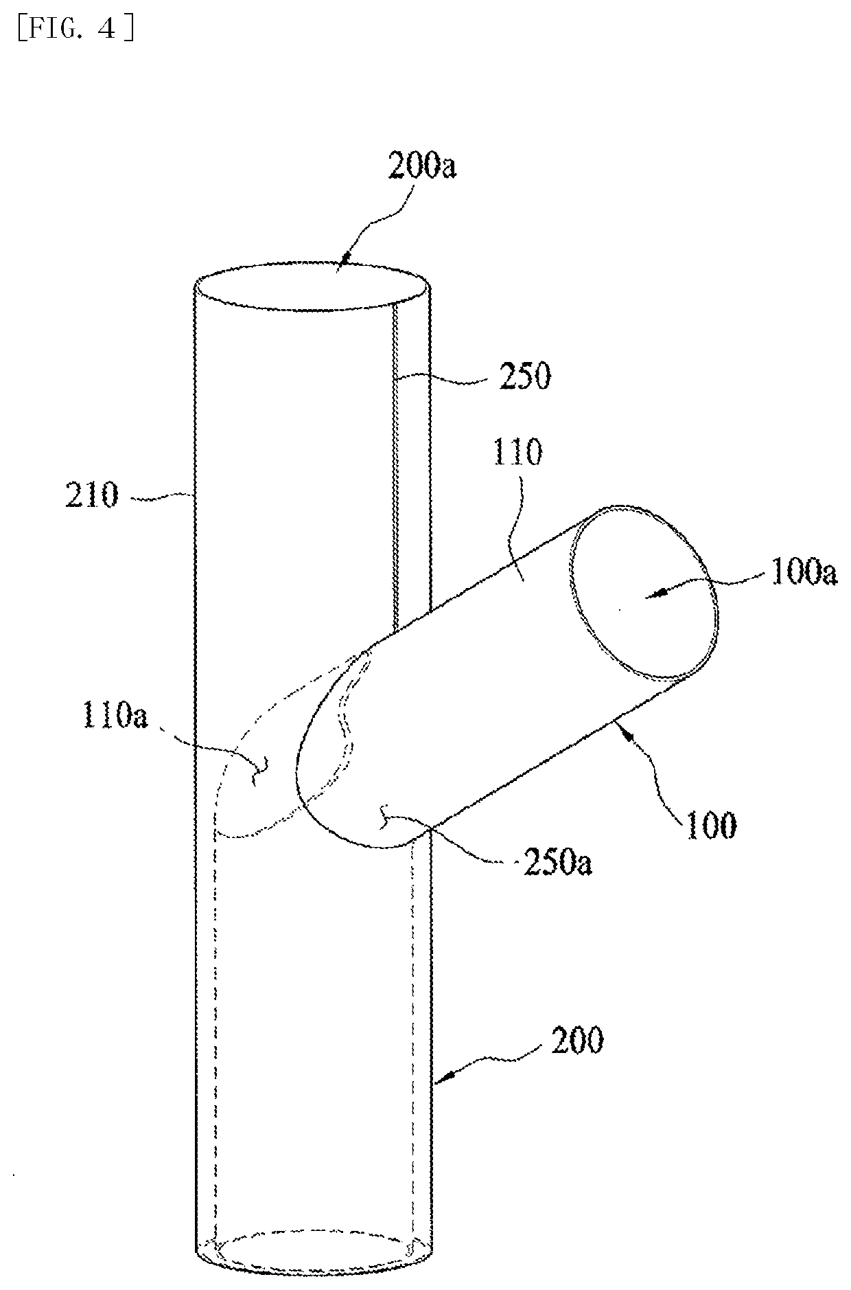
[0034]Specifically, referring to FIGS. 1 to 3, the drainage catheter according to an example of the present invention comprises a first induction conduit (100) and a second induction conduit (200).

[0035]The first induction conduit (100) and the second induction conduit (200) can be inserted, as coupled, into the bile duct (40), such that the drainage...


PUM


Abstract

The drainage catheter according to the examples of the present invention comprises a first induction conduit; and a second induction conduit having a circumference part surrounding the first induction conduit, in which a cut part is formed so that a front edge of the first induction conduit is exposed to the outside.

Description

TECHNICAL FIELD[0001]The present invention relates to a drainage catheter, and more specifically, to a drainage catheter that is installed in a branched bile duct to allow smooth discharge of bile.BACKGROUND ART[0002]Typically, when stenosis occurs in an organ that needs to have a certain internal diameter such as blood vessels, esophagus or bile ducts due to sediment or the like, a stent or catheter may be used to artificially expand the narrowed region.[0003]In particular, when stenosis occurs in a bile duct, which functions as a path for the movement of bile, a digestive enzyme produced in the liver, the diameter of the bile duct becomes narrower, which may hinder smooth discharge of bile.[0004]Therefore, a catheter may be inserted into the narrowed bile duct to widen the bile duct to have bile smoothly discharged, thereby preventing backflow of food or fluid.[0005]Referring to FIG. 1, bile ducts (40) may connect between the liver (10), the gallbladder (20), and the pancreas (30)...

Claims


Application Information

Patent Timeline
IPC IPC(8): A61M27/00
CPCA61M2210/1042A61M27/002A61M25/09A61F2/07A61F2002/041A61F2002/061A61M27/00A61M2025/0004A61M2025/018A61M2025/0188A61M2025/1045A61F2/04A61F2/95A61F2002/9511
Inventor KANG, SUNG KWONPARK, SUN SOONJUNG, SO HEE
Owner S&G BIOTECH
Why Eureka
Try Eureka