Valve grease blocks for high pressure valves and high pressure valves using the same

Active Publication Date: 2020-01-16
BLUECORE COMPLETIONS LLC
View PDF30 Cites 1 Cited by
  • Summary
  • Abstract
  • Description
  • Claims
  • Application Information

AI Technical Summary

Benefits of technology

The present invention relates to a valve grease block for combined greasing and bleeding operations that is connected to a valve. This valve grease block can support multiple grease / bleed fittings and allows flushing of all critical seal areas contained within it with clean grease, while also allowing shut off of the main grease port for replacement or maintenance of the attached or integrated greasing or bleeding fitments. The valve grease block has a low profile for minimizing the mechanical handling risk profile during operations and can be incorporated into newly designed valves or retrofitted to existing valves. The technical effects of the present invention include significant improvement over the prior art by allowing all the required stages of greasing a valve without breaking the main seal to the valve body, as well as prevention of the core failure mechanism and costly workover to temporarily plug the wellbore due to failure of the grease fitting on the valve side closest to the wellbore.

Problems solved by technology

Moreover, the fracing is typically preceded and followed by an acid wash of 15% hydrochloric acid, which accelerates corrosion.
With the high velocity of abrasive fracing fluid, any weakness or point of turbulence can very quickly lead to a washout of a seal area or any interface.
If an area or interface adjoins the valve main body, then the life of the main valve body is severely limited.
Even with this procedure, the moving sealing faces have a very limited service life and are replaced frequently, to ensure effective sealing and to prevent scouring of the seal surfaces with trapped particles.
Usually these valves do not have a dedicated grease bleed, as bleeding may need to occur at any of the same places as where the grease fittings are installed.
The practice of inserting a pin to force open the check valves can scratch the balls or seats of the check valve, which are the most commonly used type of grease check valve in fittings for high pressure applications.
The damaged balls or seats lead to leaks under very high pressures.
Sometimes when the pressure lock pressure has been bled off, the high viscosity of the sealing type grease can prevent the ball check from reseating, leading to weeping leaks.
Worst of all it is possible when displacing the valve cavity or when bleeding pressure to have grease or sealant contaminated with frac sand enter the check valves of the grease fitting causing failure.
Dedicated bleed valves do not solve the problem as they too can fail with frac sand contaminated grease.
Such a practice, as known by those skilled in the art, is inherently dangerous, given that a connection is being broken under pressure.
In addition, this technique also affects the known pressure integrity of the valve, since a pressure tested connection has been broken.
Furthermore, if sand contaminated grease should flow out, then the chances of successfully re-creating a valid metal to metal seal when screwing the grease fitting back in is substantially diminished.
The core of the problem is having a single fluid conduit for the grease or bleed operation.
Once the integrity of the fitting on this single conduit is compromised, then the barrier between the process fluid and the external environment is also compromised, an unacceptable situation for a high-pressure operation in the 21st century.
Adding dedicated bleed ports does not solve the issue, as failure of the bleed fitting can lead to the same problem.
In theory, adding an isolation valve between the valve body and the grease fitting will increase valve integrity, but this also leads to a significant protrusion from the valve body.
This is a dangerous proposition on a high maintenance operation such as a fracing job.
It also does not address the inherent root cause of the failure, which is frac sand contaminated grease inside an isolation device, whether this is a grease fitting, bleed fitting or a valve added between any of these fittings and the main valve body.

Method used


Image

  • Valve grease blocks for high pressure valves and high pressure valves using the same
  • Valve grease blocks for high pressure valves and high pressure valves using the same
  • Valve grease blocks for high pressure valves and high pressure valves using the same

Examples


Embodiment Construction

[0038]The problems being solved and the solutions provided by the embodiments of the principles of the present invention are best understood by referring to FIGS. 1 to 11 of the drawings, in which like numbers designate like parts.

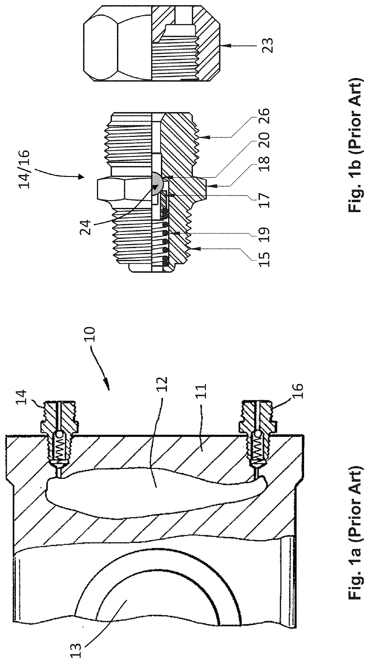
[0039]FIG. 1a shows a schematic cross-sectional view of a prior art valve assembly 10 with two identical grease fittings 14 and 16 installed. The valve internals are schematically indicated by 13, along with the valve body 11 with a valve cavity 12. This is a very common arrangement, which allows for injection of grease into the valve cavity 12 from different points through grease fittings 14 and 16.

[0040]FIG. 1b is schematic side view showing the detail of a currently commercially available prior art grease fitting suitable for use as grease fittings 14 and 16 of FIG. 1a. This fundamental design has not changed significantly over the years and includes a thread 15 for installation into the valve body 11. A hexagonal profile 18 is provided to allow install...


PUM


Abstract

A high-pressure grease block including a grease block body having a grease block cavity defined therein and adapted to cooperate with a valve body. A first port is adapted for sealing connection to a port on the valve body such that a valve grease cavity defined within the valve body communicates with the grease block cavity. A second port communicates with the grease block cavity and is adapted for receiving a greasing assembly and a third port communicates with the grease block cavity and is adapted for receiving a bleeding assembly.

Description

FIELD OF INVENTION[0001]The present invention relates in general to fluid drilling equipment and in particular to grease and bleed fittings used in high pressure valves subjected to severe operating conditions, such as the high pressures, high flow rates, and abrasive fluids commonly found in hydraulic fracturing operations and other oil and gas drilling applications.BACKGROUND OF INVENTION[0002]Grease and bleed fittings are an inherent feature of valves, especially in severe service conditions, such as high pressure, high temperature or abrasive flows. For example, grease may be used as body cavity filler to prevent unwanted accumulation of fluids or solids being passed through the valve. Some valves require high viscosity grease that acts more as a sealant for the metal sealing surfaces. These greases may have additives, such as Teflon fibers or other materials that assist in achieving a seal. Generally, the greases are injected through a grease fitting under pressure from a greas...

Claims


Application Information

Patent Timeline
IPC IPC(8): F16N21/00F16N17/00F16N23/00F16K3/36
CPCF16N23/00E21B43/26F16N17/00F16N21/00F16K3/36
Inventor HARREL, TRAVISLEUCHTENBERG, CHRISTIAN
Owner BLUECORE COMPLETIONS LLC
Why Eureka
Try Eureka