Connection assembly for transmitting loads between two wing elements

a technology of connecting assembly and wing element, which is applied in the direction of aircraft transmission means, power plants without power amplication, and power plants, etc., can solve the problems of assuming a considerable amount of space, affecting the stability of the connection, so as to reduce the stress on the mounting bolt

Active Publication Date: 2020-01-23
AIRBUS OPERATIONS GMBH
View PDF0 Cites 2 Cited by
  • Summary
  • Abstract
  • Description
  • Claims
  • Application Information

AI Technical Summary

Benefits of technology

[0017]In addition to providing two load paths, the connection assembly according to the present invention provides a robust connection between the first and the second wing element in the load plane. In particular, in the direction of the first arms of the L-shaped load-bearing devices high loads can be transferred. In other words, the connection assembly provides a high bending stiffness against rotations about a movement axis extending in the load plane and generally parallel to the extension directions of the first arms of the L-shaped load-bearing devices. If, for example, the connection assembly is used to connect a slat-track as the first wing element to a slat forming the second wing element, the connection assembly can be used to ensure that the slat is in the same deployed position in the cord direction of wing.
[0049]The limiting means provide an additional means for ensuring a second load path and limit the relative rotation of the first and second load-bearing devices relative to each other.

Problems solved by technology

At least one of the joints is configured as a so-called master joint, which does not allow for lateral displacement between the slat and the respective slat track at the location of the joint.
However, the arrangement of spherical bearings used in the joints, typically together with multiple links, is relatively complex and expensive and assumes a considerable amount of space.

Method used


Image

  • Connection assembly for transmitting loads between two wing elements
  • Connection assembly for transmitting loads between two wing elements
  • Connection assembly for transmitting loads between two wing elements

Examples


Embodiment Construction

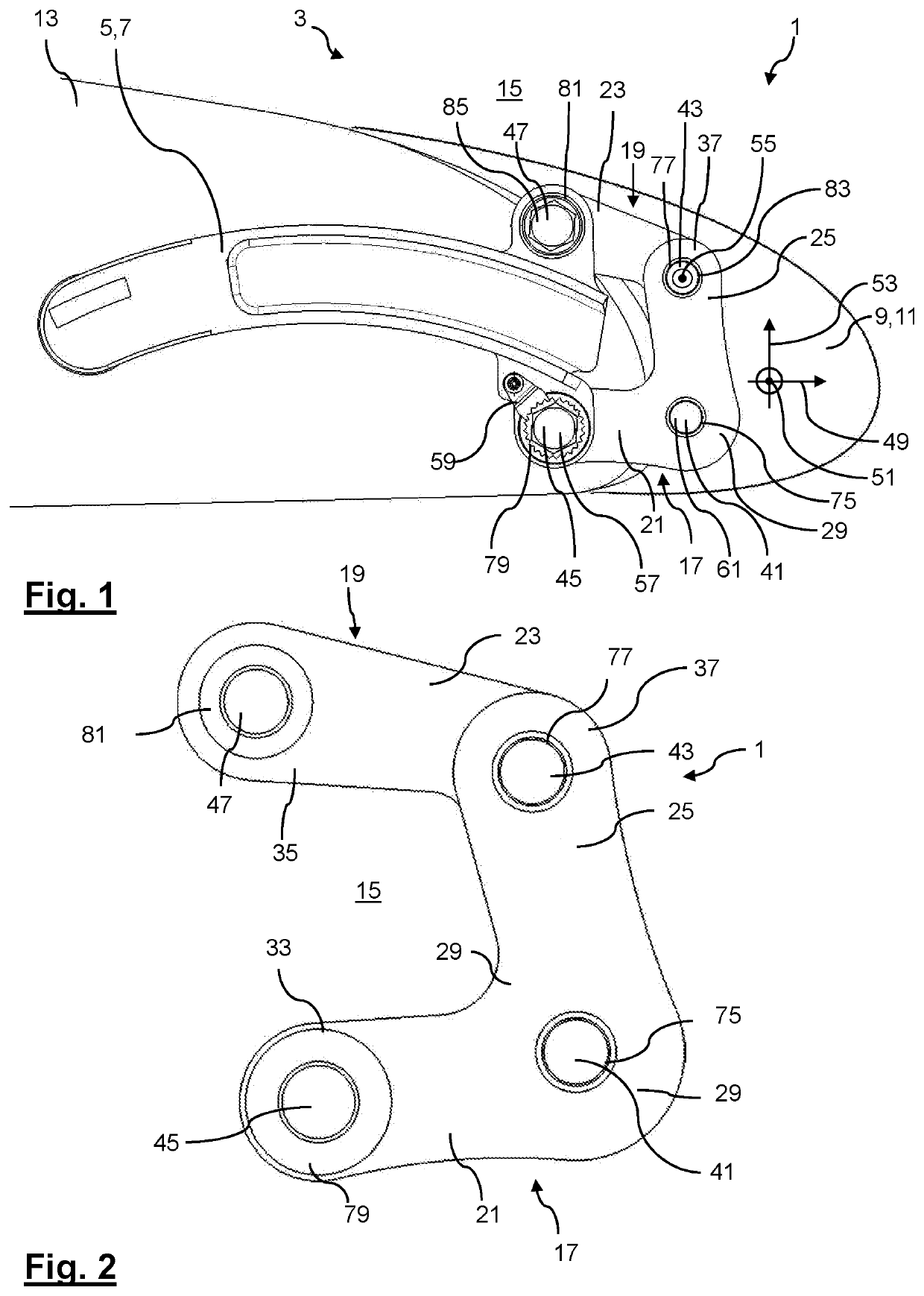
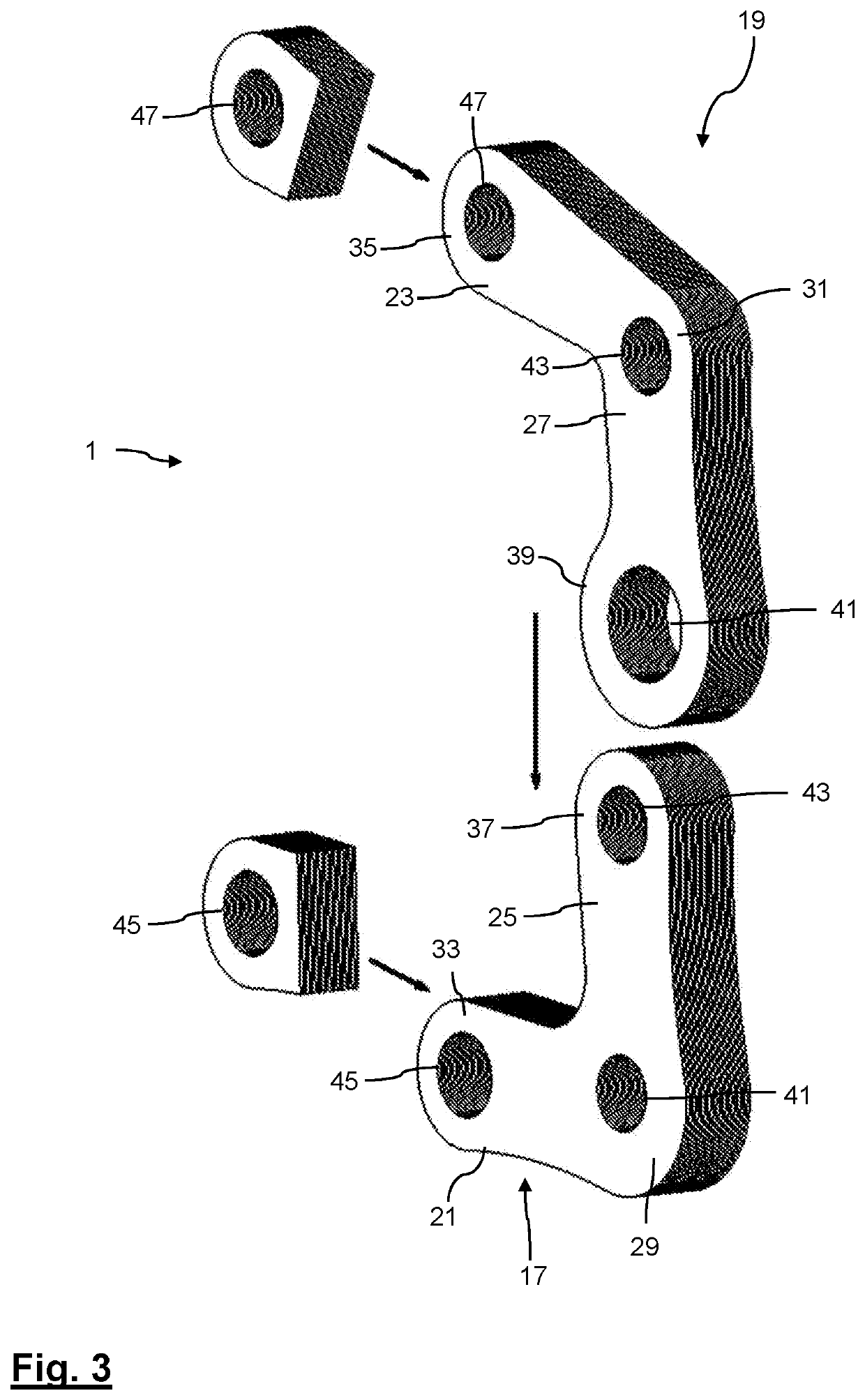
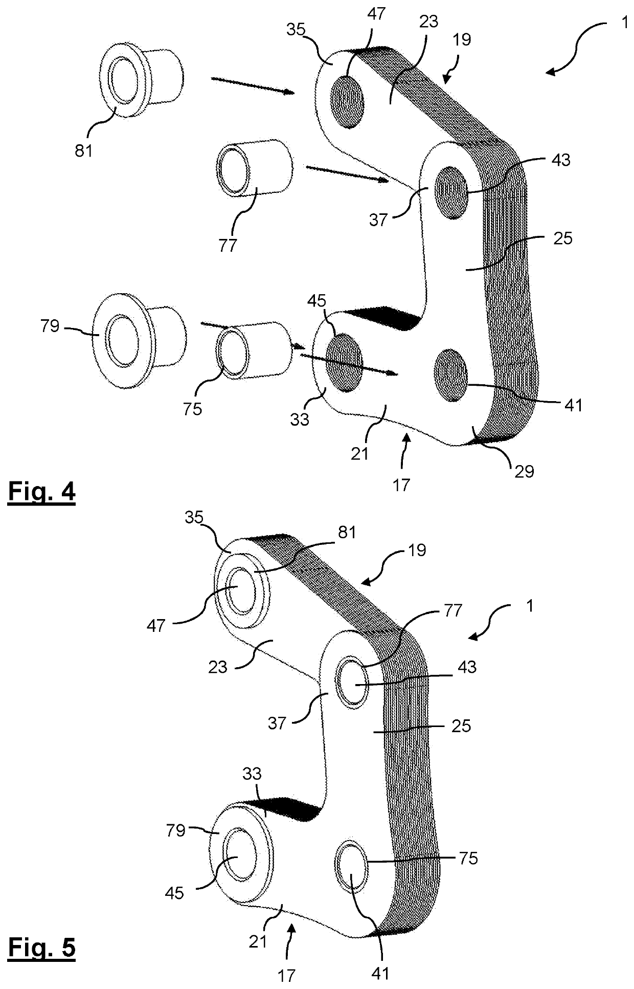
[0066]In the following, a first exemplary embodiment of a connection assembly 1 used in a slat assembly 3 will be described with reference to FIGS. 1 to 5 and 12. Throughout the Figures, like reference numerals are used to indicate like elements. Not all features of the exemplary embodiments are depicted in all Figures. In particular, the slat assembly 3 is only shown in FIG. 1, whereas the connection assembly 1 is shown in all Figures. If a feature is particularly well depicted in a specific Figure, reference will be made to that Figure. Otherwise it is understood that a Figure at least shows those features of the exemplary embodiments mentioned in the description with specific reference to that Figure unless stated otherwise.

[0067]FIG. 1 shows an exemplary embodiment of a connection assembly 1 used as part of a slat assembly 3 for connecting a first wing element 5 in form of a slat track 7 to a second wing element 9 in form of a slat 11. The slat track 7 is mounted to a main wing ...


PUM


Abstract

A C-shaped connection assembly transmits loads in a load plane between a first and a second wing element. The connection assembly comprises a first and a second L-shaped load-bearing device. Each load-bearing device comprises a joint region and two legs extending parallel to the load plane and away from the joint region towards respective end regions. One leg of the first load-bearing device extends parallel to one leg of the second load bearing device. These legs are connected to one another. Two coupling portions which connect the connection assembly to the second wing element are formed in the respective joint regions of the load-bearing devices. Two further coupling portions which connect the connection assembly to the first wing element are formed in respective free end region of the load-bearing device and the joint region of the second load-bearing device.

Description

CROSS-REFERENCES TO RELATED APPLICATIONS[0001]This application claims the benefit of the German patent application No. 102018114680.9 filed on Jun. 19, 2018, the entire disclosures of which are incorporated herein by way of reference.FIELD OF THE INVENTION[0002]The present application relates to a connection assembly for transmitting loads in a load plane between a first wing element and a second wing element. Further, the application relates to a slat assembly for a main wing of an aircraft and an aircraft comprising a slat assembly.BACKGROUND OF THE INVENTION[0003]In order to be able to selectively vary the degree of lift provided by an aircraft wing, aircraft wings are typically provided with aerodynamic surfaces which are movably coupled to a main wing such that they can be moved between a stowed position, in which they are disposed within or directly on the main wing, and at least one deployed position, in which they are extended from the main wing. Slats are such movable aerod...

Claims


Application Information

Patent Timeline
Patent Type & Authority Applications(United States)
IPC IPC(8): B64C9/02B64C13/28B64C9/26
CPCB64C13/28B64C9/26B64C2009/143B64C9/02B64C3/50B64C9/14B64C9/22
Inventor SCHLIPF, BERNHARDLORENZ, FLORIANKREY, DENNIS
Owner AIRBUS OPERATIONS GMBH
Why Eureka
Try Eureka