Observation system for dental and medical treatment

a technology for medical treatment and observation system, which is applied in the field of observation system for dental and medical treatment, can solve the problems of preventing the spread of dental treatment using the surgical microscope, affecting the accuracy of dental treatment, so as to achieve the effect of preventing excessive approaching, facilitating movement, and accurately positioning

Inactive Publication Date: 2020-01-30
ALICE VISION CORP
View PDF3 Cites 4 Cited by
  • Summary
  • Abstract
  • Description
  • Claims
  • Application Information

AI Technical Summary

Benefits of technology

[0053]Further, since either one or both of the horizontally pivoting arm and the vertical arm are provided with a telescopic structure changing an arm length, the vertical axial line of the vertically holding arm can easily be moved to and accurately positioned in the position passing through the oral cavity of the patient lying on the dental chair by changing the arm length of the horizontally pivoting arm, and the height of the display unit can easily be adjusted to an appropriate height corresponding to treatment performed by the dental surgeon by changing the arm length of the vertically fixed arm.
[0054](Advantageous Effect of Pivoting Radium of Display Unit)
[0055]Further, si

Problems solved by technology

The conventional surgical microscope involves has a structural problem due to the fact that the surgical microscope is an optical microscope.
Since the dental surgeon using the surgical microscope cannot keep the constant attitude in this manner, the dental treatment using the surgical microscope is very complicated, which results in an obstruction to the spread of the dental treatment using the surgical microscope.
In view of these circumstances, a system where an image of a video camera attached to the surgical microscope is displayed on a two-dimensional monitor or a three-dimensional monitor and performs the dental treatment while viewing the image has been tried, but such a dental treatment is not widespread at all because it is difficult to observe the image with natural three stereoscopic vision.
However, the conventional stereo viewer is considered to be unsuitable at all for the dental treatment where a treatment is performed within a narrow range on the face of a patient because the stereo viewer has a very large size, or has a small size but is remarkably poor in

Method used


Image

  • Observation system for dental and medical treatment
  • Observation system for dental and medical treatment
  • Observation system for dental and medical treatment

Examples


second embodiment

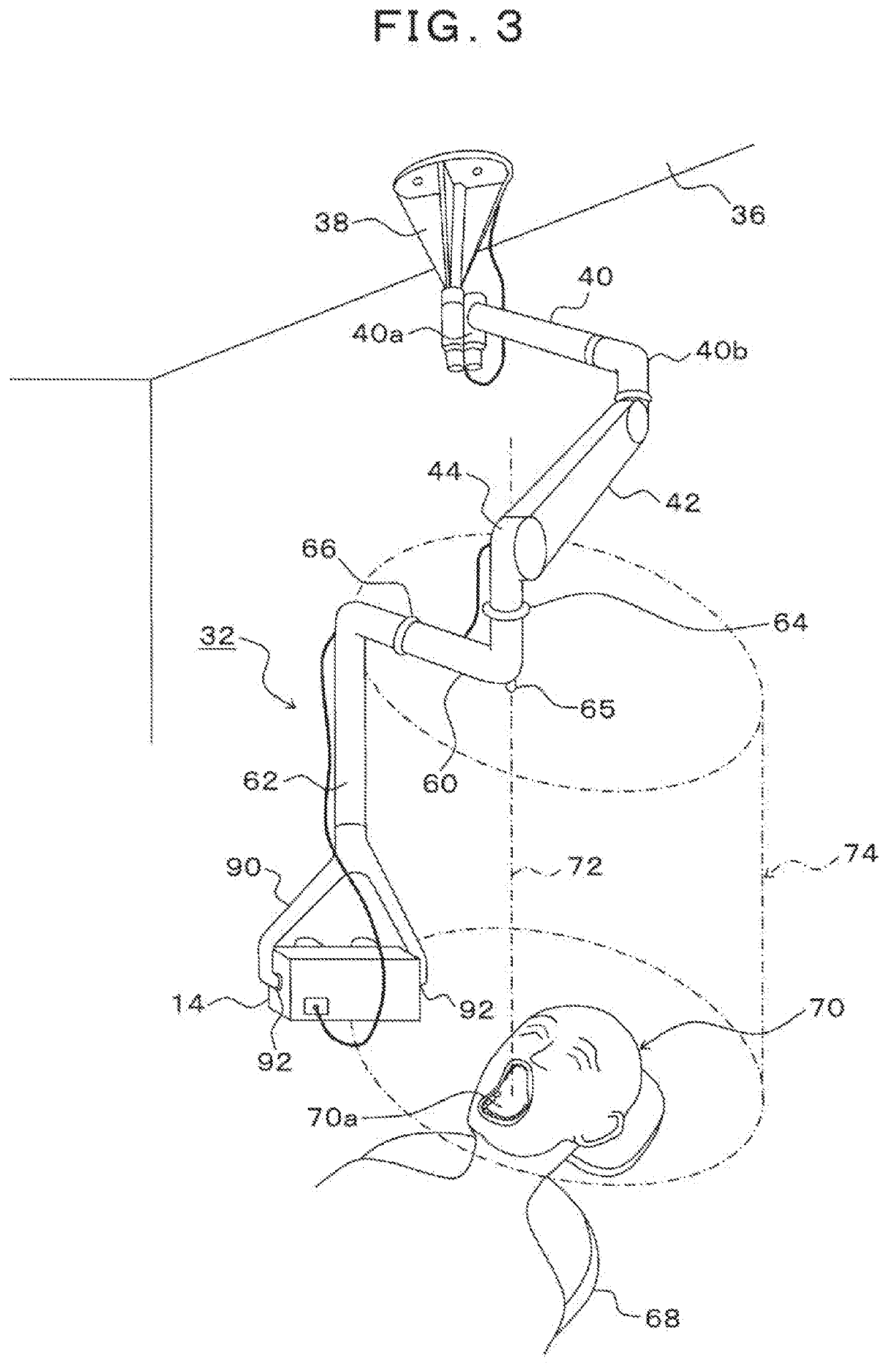
[0090]FIG. 3 is a descriptive diagram depicting the supporting mechanism, FIG. 4 is a descriptive diagram depicting a link configuration in the supporting mechanism depicted in FIG. 3, and FIGS. 5A and 5B are descriptive diagrams depicting a display unit held at a distal end of a vertically fixed arm, and FIG. 5A is a side view of the display unit and FIG. 5B is a front view thereof. FIG. 6 is a descriptive diagram depicting, in plan view, a position of the display unit held around the dental chair by the supporting mechanism depicted in FIG. 3, FIG. 7 is a descriptive diagram depicting an aspect of dental treatment performed by the observation system for dental treatment provided with the supporting mechanism depicted in FIG. 3, and FIG. 8 is a descriptive diagram depicting the supporting mechanism depicted in FIG. 3 holding the display unit when a dental surgeon performs dental treatment in his / her standing position with a backrest for the patient raised.

[0091](Configuration of Su...

first embodiment

[0092]As shown in FIG. 3, a supporting mechanism 32 of the present embodiment is composed of a base 38, a horizontally pivoting arm 40 functioning as a second horizontally pivoting arm, a parallel link arm 42, and a vertically holding arm 44, which constitute the same link configuration as the first embodiment depicted in FIG. 3, and are followed by a horizontally pivoting joint 64, a horizontally pivoting arm 60, a vertically pivoting joint 66 and a vertical arm 62.

[0093]That is, the supporting mechanism 32 of the present embodiment configures a parallel link mechanism in which a rear end side of the horizontally pivoting arm 40 is supported on the base 38 fixed on, for example, a ceiling 36 so as to be pivotable horizontally on the horizontally pivoting joint 40a, a rear end side of the parallel link arm 42 is supported on a distal end side of the horizontally pivoting arm 40 so as to be pivotable horizontally on the horizontally pivoting joint 40b, and the parallel link arm 42 mo...

third embodiment

[0137]FIG. 13 is a descriptive diagram depicting the supporting mechanism where the vertically holding arm is fixed to the base side and the vertical arm has a telescopic structure, and FIG. 14 is a descriptive diagram depicting a link configuration in the supporting mechanism depicted in FIG. 13.

[0138]As depicted in FIG. 13 and FIG. 14, the supporting mechanism 32 of the present embodiment is characterized by using the mechanism following the vertically holding arm 44 in the supporting mechanism 32 of the first embodiment depicted in FIG. 3.

[0139]That is, the supporting mechanism 32 of the present embodiment is configured such that the vertically holding arm 44 is fixed downwardly to the base 38 fixed to the ceiling face 36, and what follow the vertically holding arm 44 are basically the same as those of the second embodiment depicted in FIG. 3, so that the display unit 14 is attached via the shaft portions 92 to the forked supporting arm 90 fixed at the distal end of the vertical ...


PUM


Abstract

A supporting mechanism of an observation system for dental and medical treatment three-dimensionally movable supports a display unit for stereoscopically displaying an observation image of a surgical microscope regarding treatment of a patient on a dental chair and holds the display unit in an observation position of a dental surgeon keeping a constant posture. In a state where a vertically holding arm has been moved to a position where a vertical axial line thereof passes through an oral cavity of the patient, the supporting mechanism supports the display unit so as to be movable for positioning via a vertically fixed arm and a horizontally pivoting arm, in a position around the dental chair corresponding to a predetermined pivoting radius defined by a horizontal distance up to a finder of the display unit around the vertical axial line.

Description

BACKGROUND OF THE INVENTIONTechnical Field[0001]The preset invention relates to an observation system for a dental and medical treatment for supporting a display unit for displaying an observation image of a surgical microscope or the like regarding a treatment of a patient on a chair so that the display unit can move three-dimensionally and holding the display unit in an observation position of a dental surgeon who keeps his / her fixed posture.Description of the Related Art[0002]Conventionally, with the spread of a surgical microscope in the medical field, the surgical microscope is also introduced into dentistry, and a precise dental treatment using the surgical microscope is performed.[0003]The conventional surgical microscope involves has a structural problem due to the fact that the surgical microscope is an optical microscope. Generally, the surgical microscope is composed of an objective lens and an eyepiece lens, and these lenses are optically coupled to each other and integr...

Claims


Application Information

Patent Timeline
IPC IPC(8): A61B90/00H05K5/00H05K5/02
CPCH05K5/0217A61B2090/372A61B90/37H05K5/0017H04N5/222H04N7/18H04N13/139H04N13/189H04N13/239H04N13/344A61C19/00A61C19/04A61B2090/371A61B2090/3614A61B90/25A61B90/50A61B2090/506A61B2090/309A61B2017/00991H04N23/00H04N23/60
Inventor OKAWARA, JUNYA
Owner ALICE VISION CORP
Why Eureka
Try Eureka