Motor-operated compressor

a motor-operated compressor and compressor technology, which is applied in the direction of machines/engines, rotary/oscillating piston pump components, liquid fuel engines, etc., can solve the problems of difficult to maintain the back pressure space at an appropriate pressure, difficult to optimize the size, and limited length so as to prevent the decompression flow channel from being blocked, the cross-sectional area of the decompression flow channel is reduced, and the pressure leakage between the scroll

Inactive Publication Date: 2020-01-30
LG ELECTRONICS INC
View PDF0 Cites 1 Cited by
  • Summary
  • Abstract
  • Description
  • Claims
  • Application Information

AI Technical Summary

Benefits of technology

[0039]In the electric compressor according to the present disclosure, since the decompression portions are configured in multi-stages between the discharge space and the back pressure space, gas oil moving from the discharge space to the back pressure space may be effectively decompressed.
[0040]Thus, since the pressure of the back pressure space may be reduced to an appropriate pressure, pressure leakage between the scrolls and frictional loss may be suppressed. Also, since the decompression portions are separated in multiple stages and the decompression rates of the decompression portions are appropriately adjusted, pressure of the gas oil supplied to the back pressure space may be reduced to an appropriate pressure, and thus, pressure of the back pressure space may be more appropriately maintained.
[0041]Further, since the plurality of decompression portions have the long decompression flow channel, the cross-sectional area of the decompression flow channel may be formed relatively large, thereby preventing the decompression flow channel from being clogged by foreign substances, enhancing reliability of the compressor.
[0042]Further, since the decompression portions are formed using existing components such as a gasket or a back pressure plate, the number of components may be reduced, as compared with a case where a separate decompression device is provided, so that manufacturing cost may be reduced.
[0043]Further, by providing the discharge passage and the decompression portions between the back pressure space and the suction space, the pressure of the back pressure space may form a dynamic pressure, so that the gas oil may be smoothly supplied to the back pressure space and pressure of the gas oil discharged to the suction space may be further lowered to suppress suction loss.

Problems solved by technology

Furthermore, the related art decompression device is configured by inserting a component such as an orifice or a spiral bolt in the middle of the back pressure flow channel, and thus, the length of a decompression flow channel may be limited.
As a result, it is difficult to optimize the size of the decompression flow channel, which makes it difficult to maintain the back pressure space at an appropriate pressure.
Particularly, in case where a CO2 refrigerant is applied to form a discharge pressure of 100 bar or higher, a decompression effect with respect to the gas oil is further lowered compared with a case where another refrigerant (e.g., R134a or R410a) is applied, having a greater difficulty in appropriately maintaining pressure of the back pressure space.
However, as the size of the decompression flow channel is reduced to be small, the decompression flow channel may be clogged with a foreign object.
If the decompression passage is clogged, oil shortage occurs in a sliding portion to increase frictional loss or degrade performance of the compressor, or major components of the compressor may be damaged due to burning.
Further, in the related art decompression device, additional components such as an orifice or a spiral bolt are additionally provided in the back pressure flow channel to form the decompression flow channel, which, however, increases the number of components for constituting the decompression device to increase manufacturing cost.

Method used


Image

  • Motor-operated compressor
  • Motor-operated compressor
  • Motor-operated compressor

Examples


Embodiment Construction

[0059]Hereinafter, an electric compressor according to the present disclosure will be described in detail with reference to an embodiment illustrated in the accompanying drawings.

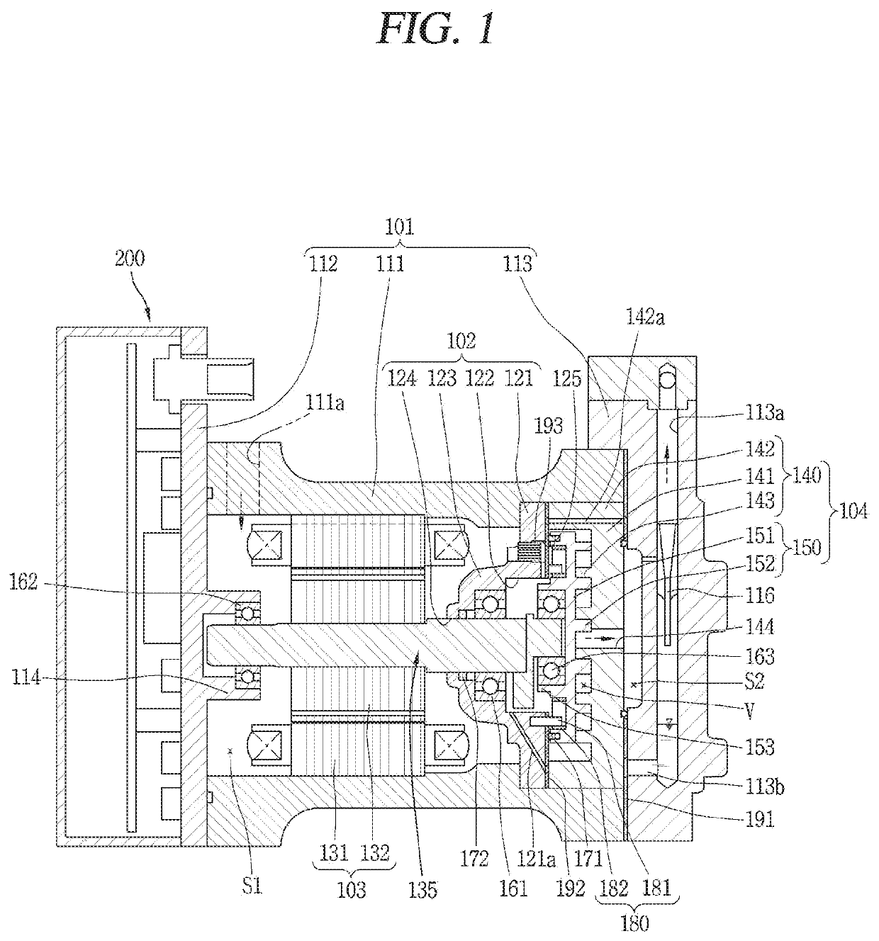
[0060]An electric compressor according to the present disclosure, a part of a refrigerating cycle device for sucking and compression a refrigerant, is a scroll compressor in which two scrolls are engaged to compress a refrigerant. In this embodiment, a high temperature and high pressure electric scroll compressor in which a discharge pressure is 100 bar, specifically, substantially 130 bar, and a discharge temperature is approximately 170° C. using a carbon dioxide (CO2) refrigerant will be described for example. FIG. 1 is a cross-sectional view of an electric compressor according to the present disclosure.

[0061]Referring to FIG. 1, an electric compressor according to the present embodiment may include a casing 101, a main frame 102, a driving unit 103, and a compression unit 104. Also, an inverter unit 200...


PUM


Abstract

An electric compressor includes a main housing including a motor chamber. The motor chamber includes a driving motor. The compressor includes a frame fixed to one end of the main housing, a first scroll supported by one side surface of the frame, and a second scroll provided between the frame and the first scroll. The second scroll, supported by the frame, makes an orbiting motion upon receiving a rotational force from the driving motor. The second scroll also forms a compression chamber with the first scroll and a back pressure space with the frame. A rear cover coupled to the main housing forms a discharge space with the first scroll. A back pressure flow channel extends through the first scroll and the frame to guide a refrigerant and oil from the compression chamber to the discharge and back pressure spaces. The compressor also includes a plurality of decompression portions.

Description

CROSS-REFERENCE TO RELATED APPLICATION[0001]Pursuant to 35 U.S.C. § 119(a), this application claims the benefit of earlier filing date and right of priority to Korean Application No. 10-2018-0088121, filed on Jul. 27, 2018, the contents of which are incorporated by reference herein in their entirety.BACKGROUND OF THE INVENTION1. Field of the Invention[0002]The present disclosure relates to a scroll type motor-operated compressor.2. Background of the Invention[0003]Generally, compressors for compressing a refrigerant in automotive air conditioning systems have been developed in various forms. Recently, motor-operated compressors (or electric compressors) driven by electricity using motors have been actively developed as automotive parts tend to become electronic / electric components.[0004]A scroll compression method suitable for a high compression ratio operation is mainly applied to electric compressors. In a scroll type electric compressor (hereinafter, referred to as an ‘electric c...

Claims


Application Information

Patent Timeline
Patent Type & Authority Applications(United States)
IPC IPC(8): F04C18/02F04C23/00F04C27/00F04C29/02F04C29/04
CPCF04C18/0215F04C29/045F04C29/026F04C29/028F04C27/005F04C23/008F04C18/0261F04C29/0021F04C2240/30F04C2240/70
Inventor KIM, JOOHYUNGNAM, SANGHOONPARK, TAESANGCHOI, YICHEOL
Owner LG ELECTRONICS INC
Why Eureka
Try Eureka