Substrate treating apparatus

a technology for treating apparatus and substrates, which is applied in lighting and heating apparatus, drying machines with progressive movements, and cleaning using liquids. it can solve the problems of low throughput of substrate treatment from treatment with treating liquid, inability to clean substrates, and inability to dry substrates. the effect of reducing the cost of the apparatus and reducing the construction complexity

Active Publication Date: 2009-03-24
DAINIPPON SCREEN MTG CO LTD
View PDF6 Cites 1 Cited by
  • Summary
  • Abstract
  • Description
  • Claims
  • Application Information

AI Technical Summary

Benefits of technology

[0009]This invention has been made having regard to the state of the art noted above, and its object is provide a substrate treating apparatus that enables draining of water even under decompression by adjusting pressure inside and outside a chamber, thereby treating substrates in a clean state while assuring improved throughput of substrate treatment.
[0011]According to this invention, the control device fills the chamber with a solvent atmosphere, causes the holding mechanism to move the substrates from the treating position to the drying position, operates the first decompressing device to decompress the chamber to the first pressure, and operates the second decompressing device to adjust the pressure in the buffer tank to the second pressure equal to or lower than the first pressure before the treating liquid in the treating tank is discharged into the buffer tank. Thus, the pressure in the chamber and the pressure in the buffer tank are equal, or the pressure in the buffer tank is lower. Therefore, even in the decompressed solvent atmosphere, the treating liquid can be discharged from the treating tank to the buffer tank, to improve the throughput of substrate treatment. Moreover, since there is no need for pressurization inside the chamber, the substrates can be dried clean without being adversely influenced by pressurization.
[0013]According to this invention, the control device fills the chamber with a solvent atmosphere, causes the holding mechanism to move the substrates from the treating position to the drying position, operates the first decompressing device to decompress the chamber to the first pressure, and operates the second decompressing device to adjust the pressure in the buffer tank to the second pressure equal to or lower than the first pressure before the treating liquid discharged into the chamber is discharged into the buffer tank. Thus, the pressure in the chamber and the pressure in the buffer tank are equal, or the pressure in the buffer tank is lower. Therefore, even if the chamber is filled with the decompressed solvent atmosphere, the treating liquid can be discharged from the chamber to the buffer tank to improve the throughput of substrate treatment. Moreover, since there is no need for pressurization inside the chamber, the substrates can be dried clean without being adversely influenced by pressurization.
[0015]Since the pressure in the chamber and the pressure in the buffer tank are adjusted at different times, the first compressing device and second compressing device can be combined into one. Thus, the construction can be simplified, and the cost of the apparatus can be reduced.
[0017]The chamber may be decompressed efficiently by effecting decompression through the filling pipes also.

Problems solved by technology

In the conventional apparatus, deionized water stored in the treating tank inside the decompressed chamber could have an adverse influence on drying treatment of the substrates.
That is, since the water cannot be drained during decompression of the chamber, there is a problem of low throughput of substrate treatment from treatment with the treating liquid to drying treatment.
This poses a different problem that the substrates cannot be dried clean.

Method used


Image

  • Substrate treating apparatus
  • Substrate treating apparatus
  • Substrate treating apparatus

Examples


embodiment 1

[0023]Embodiment 1 of this invention will be described hereinafter with reference to the drawings.

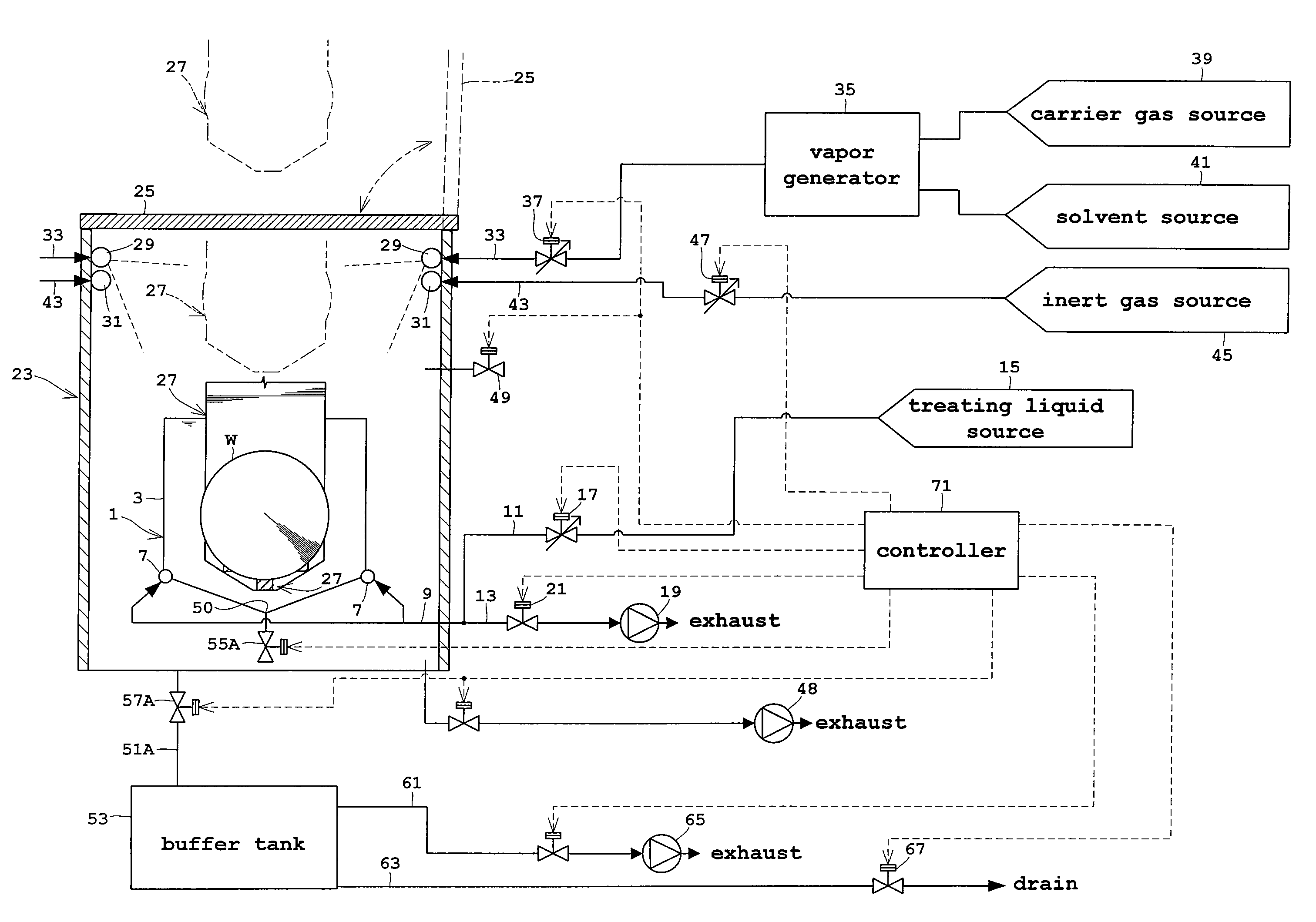
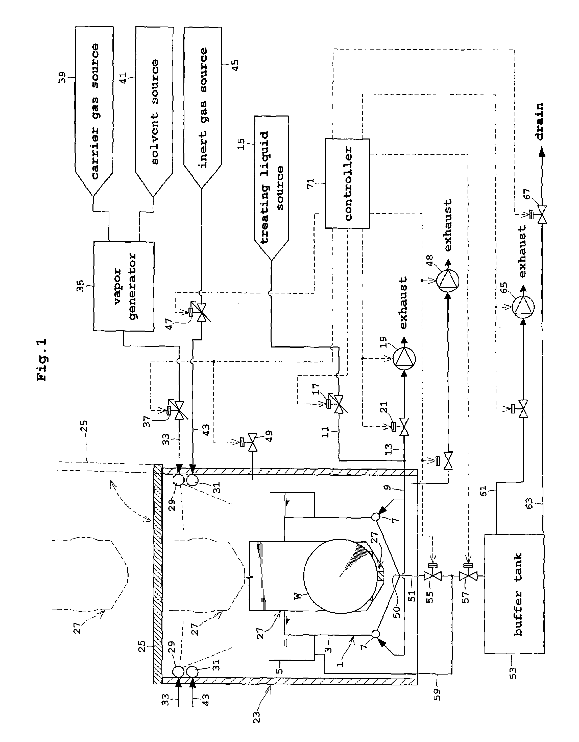
[0024]FIG. 1 is a block diagram showing an outline of a substrate treating apparatus in Embodiment 1.

[0025]The substrate treating apparatus in this embodiment has a treating tank 1 for storing treating liquids. The treating tank 1 includes an inner tank 3 for storing the treating liquids and receiving wafers W, and an outer tank 5 for collecting the treating liquids overflowing the inner tank 3. The inner tank 3 has two filling pipes 7 disposed in the bottom thereof for supplying the treating liquids into the inner tank 3. The filling pipes 7 are connected to piping 9. The piping 9 forks into a feed pipe 11 and a suction pipe 13. The feed pipe 11 is connected to a treating liquid source 15, and has a treating liquid valve 17 consisting of a control valve for controlling a flow rate through the feed pipe 11. The suction pipe 13 is connected to a first vacuum pump 19, and is opened and cl...

embodiment 2

[0047]Next, Embodiment 2 of this invention will be described with reference to the drawings.

[0048]FIG. 3 is a block diagram showing an outline of a substrate treating apparatus in Embodiment 2. Like reference numerals are used to identify like parts which are the same as in Embodiment 1 and will not be described again.

[0049]The substrate treating apparatus in Embodiment 2 is different from the construction in Embodiment 1 in the following points.

[0050]That is, the treating tank 1 has only the inner tank 3, and not the outer tank 5. A QDR valve 55A is connected to the outlet port 50 of the inner tank 3. When the QDR valve 55A is opened, a treating liquid in the inner tank 3 is once discharged to the inside of the chamber 23. The chamber 23 has a drain pipe 51A attached to the bottom thereof and connected to the buffer tank 53. The drain pipe 51A has a drain valve 57A mounted thereon. By opening this drain valve 57A, the treating liquid stored in the bottom of the chamber 23 is discha...


PUM


Abstract

A substrate treating apparatus for drying substrates by moving the substrates out of a treating liquid into a solvent atmosphere. The apparatus includes a treating tank for storing the treating liquid, a chamber enclosing the treating tank, a holding mechanism for holding the substrates, the holding mechanism being vertically movable between a treating position in the treating tank and a drying position in the chamber and above the treating tank, a supply device for supplying vapor of a solvent into the chamber, a buffer tank disposed outside the chamber for collecting the treating liquid discharged from the treating tank, a first vacuum pump for decompressing the chamber, a second vacuum pump for decompressing the buffer tank, and a controller for operating the supply device to fill the chamber with the solvent atmosphere, operating the holding mechanism to move the substrates from the treating position to the drying position, operating the first vacuum pump to decompress the chamber to a first pressure, and operating the second vacuum pump to adjust a pressure in the buffer tank to a second pressure equal to or lower than the first pressure before the treating liquid in the treating tank is discharged into the buffer tank.

Description

BACKGROUND OF THE INVENTION[0001](1) Field of the Invention[0002]This invention relates a substrate treating apparatus for drying substrates such as semiconductor wafers or glass substrates for liquid crystal displays (hereinafter called simply substrates). More particularly, the invention relates to a technique for drying substrates by moving the substrates out of a treating liquid into a solvent atmosphere while a chamber of the solvent atmosphere is decompressed.[0003](2) Description of the Related Art[0004]A conventional apparatus of this type includes a treating tank for storing deionized water, a chamber enclosing the treating tank, a holding mechanism for vertically moving substrates between a treating position inside the treating tank and a drying position above the treating tank, nozzles for supplying a vapor of isopropyl alcohol (IPA) into the chamber, a vacuum pump for decompressing the chamber, and a drain pipe for discharging the deionized water from the treating tank t...

Claims


Application Information

Patent Timeline
Patent Type & Authority Patents(United States)
IPC IPC(8): F26B13/10
CPCH01L21/67028H01L21/67034Y10S134/902H01L21/02H01L21/304
Inventor AIHARA, TOMOAKI
Owner DAINIPPON SCREEN MTG CO LTD
Why Eureka
Try Eureka