Eureka AIR delivers breakthrough ideas for toughest innovation challenges, trusted by R&D personnel around the world.

Method for repairing incomplete 3D depth image using 2d image information

a 3d depth image and depth image technology, applied in image enhancement, image analysis, instruments, etc., can solve problems such as noise and produce broken point clouds

Active Publication Date: 2020-01-30
NAT CENT UNIV
View PDF0 Cites 6 Cited by
  • Summary
  • Abstract
  • Description
  • Claims
  • Application Information

AI Technical Summary

Benefits of technology

The present invention provides a way to fix incomplete 3D depth images using 2D information to reduce distortion caused by lack of depth information in some 3D images. The method can effectively identify and repair defects in 3D images, making it efficient and economical.

Problems solved by technology

The aforesaid two techniques, however, are subject to noise in the environment (the most common example of which is infrared noise) and may produce broken point clouds as a result.
It is therefore an important issue in the related industry to develop an algorithm that can restore an incomplete point cloud of an object according to 2D image information regarding the position, surface, and boundary of the object.

Method used


Image

  • Method for repairing incomplete 3D depth image using 2d image information
  • Method for repairing incomplete 3D depth image using 2d image information
  • Method for repairing incomplete 3D depth image using 2d image information

Examples


first embodiment

[0037]The step of performing 3D reconstruction (S30) is described below with reference to FIG. 6A and FIG. 6B, which show the first embodiment S301 of performing 3D reconstruction on a selected 3D reconstruction block 310 for example. The step of performing 3D reconstruction (S301) includes the sub-steps of: defining a frame matrix (S310), establishing an initial-depth matrix (S320), and performing 3D depth image reconstruction (S330).

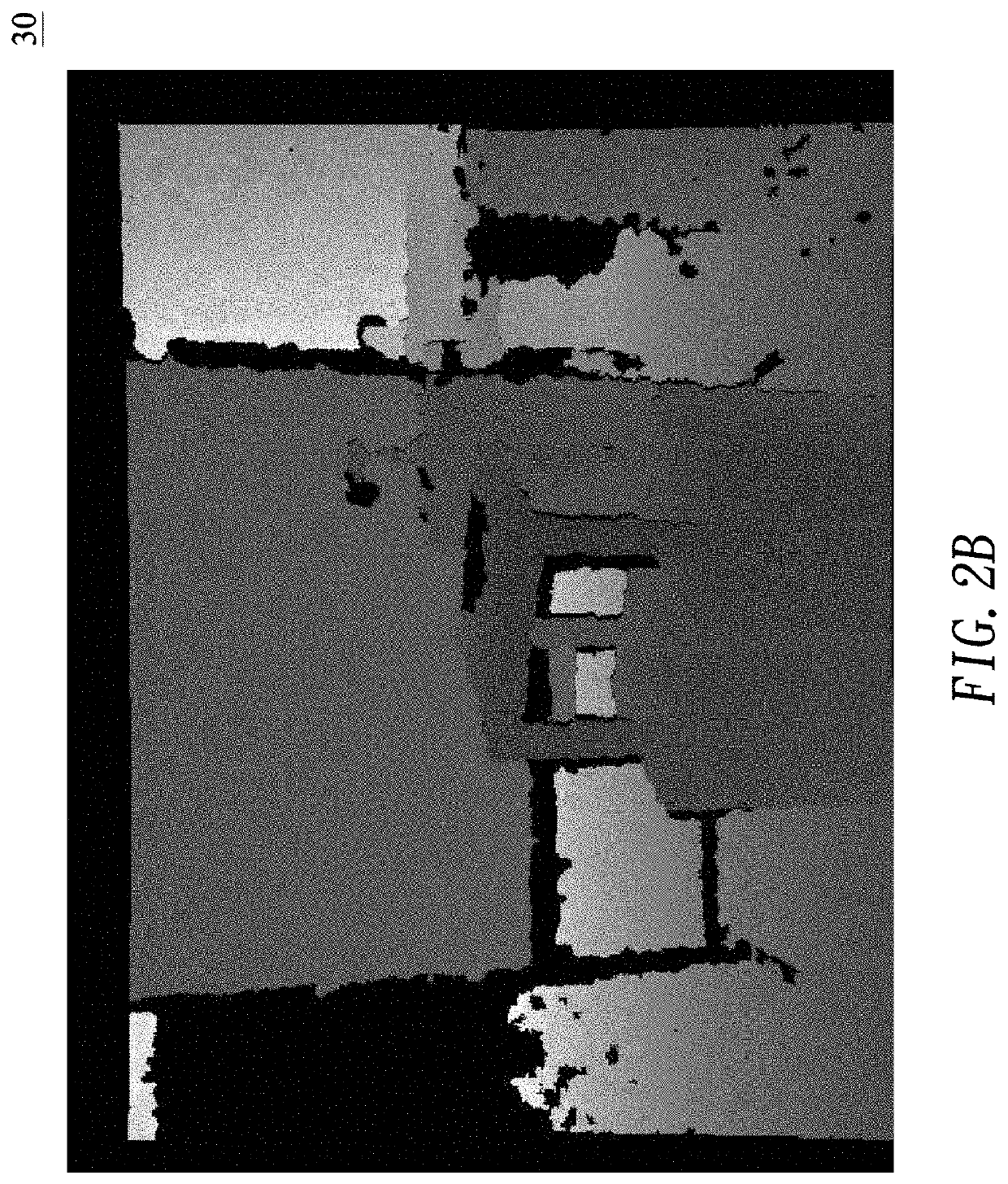
[0038]FIG. 6B shows an example of how to generate a computational frame matrix 332. In this example, a partial depth image 331, which corresponds to the selected 3D reconstruction block 310, is taken from the 3D depth image information 30 and corresponds to the computational frame matrix 332. A partial enlarged view 332A of the computational frame matrix 332 is also shown in FIG. 6B to enable better understanding of the contents of the computational frame matrix 332.

[0039]More specifically, the sub-step of defining a frame matrix (S310) is carried out ...

second embodiment

[0056]FIG. 7D shows the second embodiment S330B of the sub-step of performing 3D depth image reconstruction (S330). The 3D depth image reconstruction sub-step (S330B) includes: performing the Nth extension (S331), generating a first temporary depth matrix (S334), generating a second initial-depth matrix (S335), correcting the N+1th-computation depth matrix (S336), and repeating the 3D depth image reconstruction sub-step (S337).

[0057]FIG. 7E shows the partial 3D depth image corresponding to an N+1th-computation depth matrix 333N1, an enlarged view of the partial 3D depth image, and the N+1th-computation depth matrix itself. Performing the Nth extension (S331) is a repairing process involving extending the Nth-computation depth matrix 333N to generate the N+1th-computation depth matrix 333N1. The N+1th-computation depth matrix 333N1 is the result of the first repair.

[0058]FIG. 7F shows an example of how to generate a first temporary depth matrix. In this example, a partial 3D depth im...


PUM


Abstract

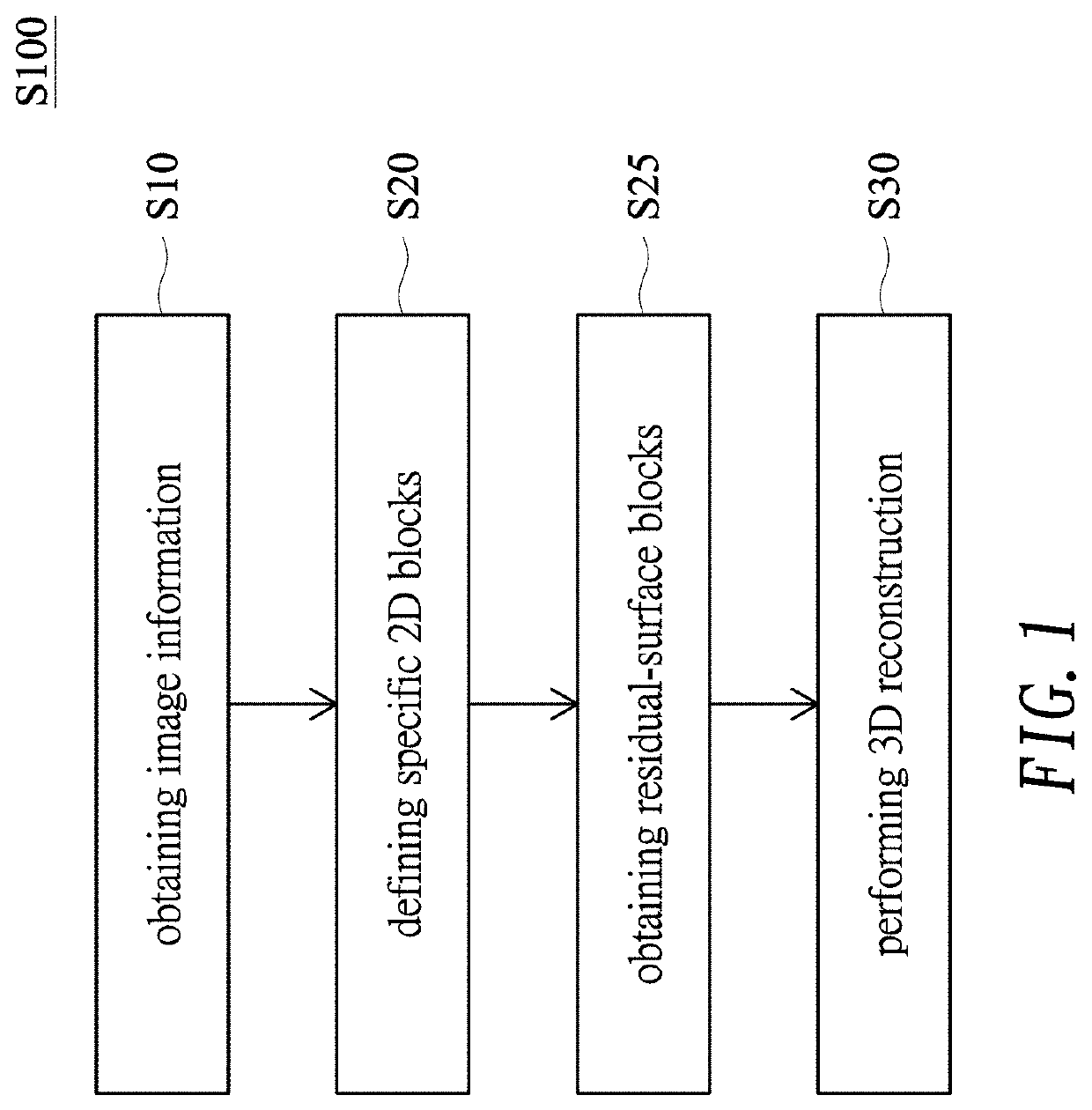
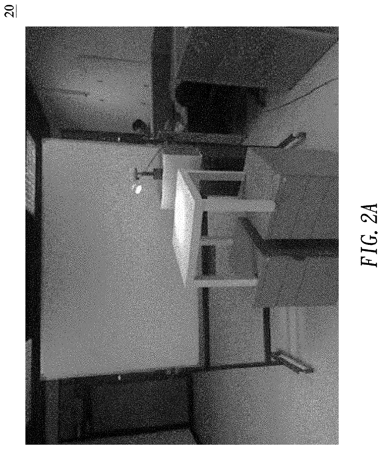
The present invention provides a method for repairing incomplete 3D depth image using 2D image information. The method includes the following steps: obtaining 2D image information and 3D depth image information; dividing 2D image information into 2D reconstruction blocks and 2D reconstruction boundaries, and corresponding to 3D reconstruction of blocks and 3D reconstruction boundaries; analyzing each 3D reconstruction block, partitioning into residual-surface blocks and repaired blocks; and proceeding at least one 3D image reconstruction, which extends with the initial depth value of the 3D depth image of each of the residual-surface block and covers all the corresponding repaired block to form a repair block and to achieve the purpose of repairing incomplete 3D depth images using 2D image information.

Description

BACKGROUND OF THE INVENTION1. Technical Field[0001]The present invention relates to a method for repairing an incomplete 3D depth image using 2D image information. More particularly, the invention relates to a method applied to a 3D image capture system to repair incomplete 3D depth images using 2D image information.2. Description of Related Art[0002]From black-and-white to color, from analog to high-definition (HD), display devices have evolved at astounding speed since their invention less than a century ago, but all the displays on the current market are still planar ones. The advent of three-dimensional (3D) images has given rise to the need to display images with depths.[0003]Nowadays, color 3D image scanning generally requires the use of two types of modules, namely color camera modules for capturing two-dimensional (2D) images and modules for capturing 3D spatial information, the latter of which typically employ the structured light technique or the time of flight (TOF) techn...

Claims


Application Information

Patent Timeline
IPC IPC(8): G06T15/04G06T19/20
CPCG06T2200/04G06T19/20G06T15/04G06T19/00G06T5/50G06T2207/10028G06T2207/10024G06T5/77
Inventor YU, YEH-WEILAU, CHI-CHUNGSUN, CHING-CHERNGYANG, TSUNG-HSUNWANG, TZU-KAIWANG, JIA-CHINGWANG, CHIEN-YAOWANG, KUAN-CHUNG
Owner NAT CENT UNIV
Why Eureka
Eureka Blog
Learn More