
Engagement and disengagement with external gear box style pumps

a gear box and pump technology, applied in the direction of piston pumps, pump control, borehole/well accessories, etc., can solve the problems of complex planning for fracturing operations, extensive equipment investment, and large investment in labor and fuel

Pending Publication Date: 2020-02-06
TYPHON TECH SOLUTIONS (U S) LLC
View PDF5 Cites 175 Cited by
  • Summary
  • Abstract
  • Description
  • Claims
  • Application Information

AI Technical Summary

Benefits of technology

The patent describes a fracturing transport that uses a gear box to connect a pump to a prime mover. The gear box has a dual shaft that connects to the pump, and an engagement coupling that can be engaged or disengaged to control the connection. This design allows for easy and quick engagement and disengagement of the pump, and is useful in oil field applications where fracturing equipment needs to be moved around frequently. The patent also describes different variations of the fracturing transport that have specific technical effects, such as a more compact design or improved mechanical efficiency. Overall, the patent presents a solution for quickly and easily connecting and disengaging equipment in the oil field.

Problems solved by technology

Implementing fracturing operations at well sites requires extensive investment in equipment, labor, and fuel.
A typical fracturing operation uses fracturing equipment, personnel to operate and maintain the fracturing equipment, large amounts of fuel to power the fracturing operations, and relatively large volumes of fracturing fluids.
As such, planning for fracturing operations is complex and encompasses a variety of logistical challenges that include minimizing the on-site area or “footprint” of the fracturing operations, providing adequate power and / or fuel to continuously power the fracturing operations, increasing the efficiency of the hydraulic fracturing equipment, and reducing the environmental impact resulting from fracturing operations.

Method used


Image

  • Engagement and disengagement with external gear box style pumps
  • Engagement and disengagement with external gear box style pumps
  • Engagement and disengagement with external gear box style pumps

Examples


Embodiment Construction

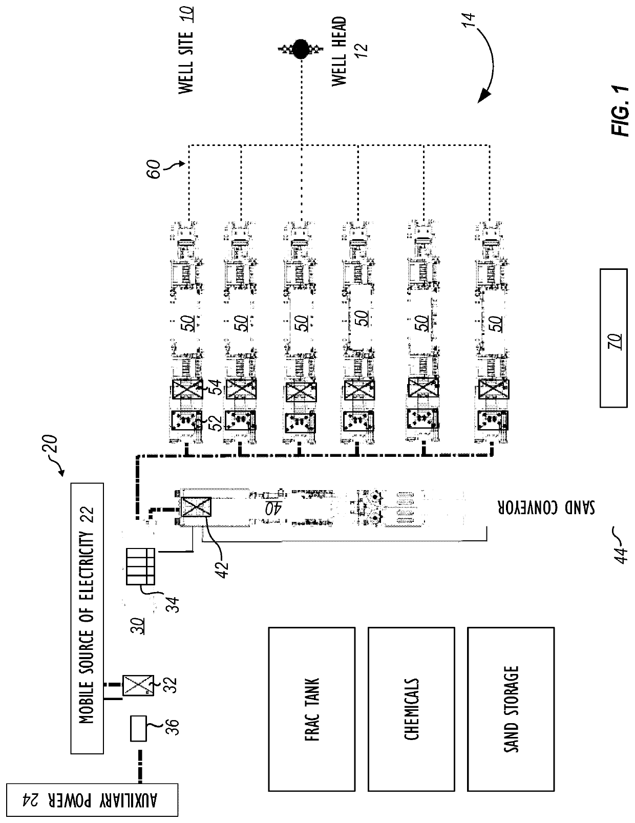
[0033]FIG. 1 is a schematic diagram of a fracturing fleet 14 located at a well site 10 having one or more wellheads 112. In this example, the fracturing fleet 14 includes one or more power sources 20, a switch gear transport 30, a blender-hydration transport 40, and one or more fracturing pump transports 50. As will be appreciated, other arrangements are possible.

[0034]The switch gear transport 30 has one or more transformers 32 and one or more circuit breakers 34 in electrical communication with the one or more power sources 20 of electricity, such as a mobile source 22 and an auxiliary source 24. In turn, the switch gear transport 30 is in electrical communication with one or more power consumers, such as a hydration-blender transport 40 and one or more fracturing pump transports 50.

[0035]Briefly, the switch gear transport 20 may include a black start generator 36 that provides electric power to initiate and start at least one of the one or more power sources 20 of electricity. Fo...


PUM


Abstract

A system and a method for producing fracturing fluid, comprising: engaging an engagement coupling attached to one end of a gear box dual shaft to a gear box connector of an external gear box, wherein the external gear box is part of a pump; rotating the gear box dual shaft to drive the pump after engaging the engagement coupling with the gear box connector; disengaging the engagement coupling from the gear box connector; and rotating the gear box dual shaft without driving the pump after disengaging the engagement coupling with the gear box connector.

Description

CROSS-REFERENCE TO RELATED APPLICATIONS[0001]This application claims the benefit of U.S. Prov. Appl. Nos. 62 / 715,165 filed 6 Aug. 2018 and 62 / 786,174 filed 28 Dec. 2018, which are both incorporated herein by reference in their entireties.BACKGROUND[0002]Hydraulic fracturing has been commonly used by the oil and gas industry to stimulate production of hydrocarbon producing wells, such as oil and / or gas wells. Hydraulic fracturing, sometimes called “fracing” or “fracking” is the process of injecting fracturing fluid into a wellbore to fracture the subsurface geological formations and release hydrocarbons. The fracturing fluid is pumped into a wellbore at a pressure sufficient to cause fissures within the underground geological formations. Once inside the wellbore, the fracturing fluid fractures the underground formation. The fracturing fluid may include water, various chemical additives, and proppants that promote the extraction of the hydrocarbon reserves, such as oil and / or gas. Pro...

Claims


Application Information

Patent Timeline
Patent Type & Authority Applications(United States)
IPC IPC(8): F04B23/04F04B17/05F04B17/03E21B43/26
CPCE21B43/26F04B17/05F04B23/04F04B17/03F04B49/02F04B9/02F04B17/06F04B23/06E21B43/2607
Inventor MORRIS, JEFFREY G.
Owner TYPHON TECH SOLUTIONS (U S) LLC
Learn More