Protective member forming apparatus

a technology of protective member and forming apparatus, which is applied in the direction of coating, manufacturing tools, lapping machines, etc., can solve the problem of difficult to generate a wafer with uniform thickness

Active Publication Date: 2020-02-06
DISCO CORP
View PDF0 Cites 0 Cited by
  • Summary
  • Abstract
  • Description
  • Claims
  • Application Information

AI Technical Summary

Benefits of technology

[0015]In this configuration, recesses and projections according to the bumps of the wafer are formed in the adhesive tape. However, the protective member absorbs the recesses and projections, and therefore the surface held in the grinding processing can be planarized. Furthermore, the direct contact of the protective member with the bumps on the lower surface of the wafer can be avoided. This can s

Problems solved by technology

For this reason, it becomes difficult to

Method used


Image

  • Protective member forming apparatus
  • Protective member forming apparatus
  • Protective member forming apparatus

Examples


Embodiment Construction

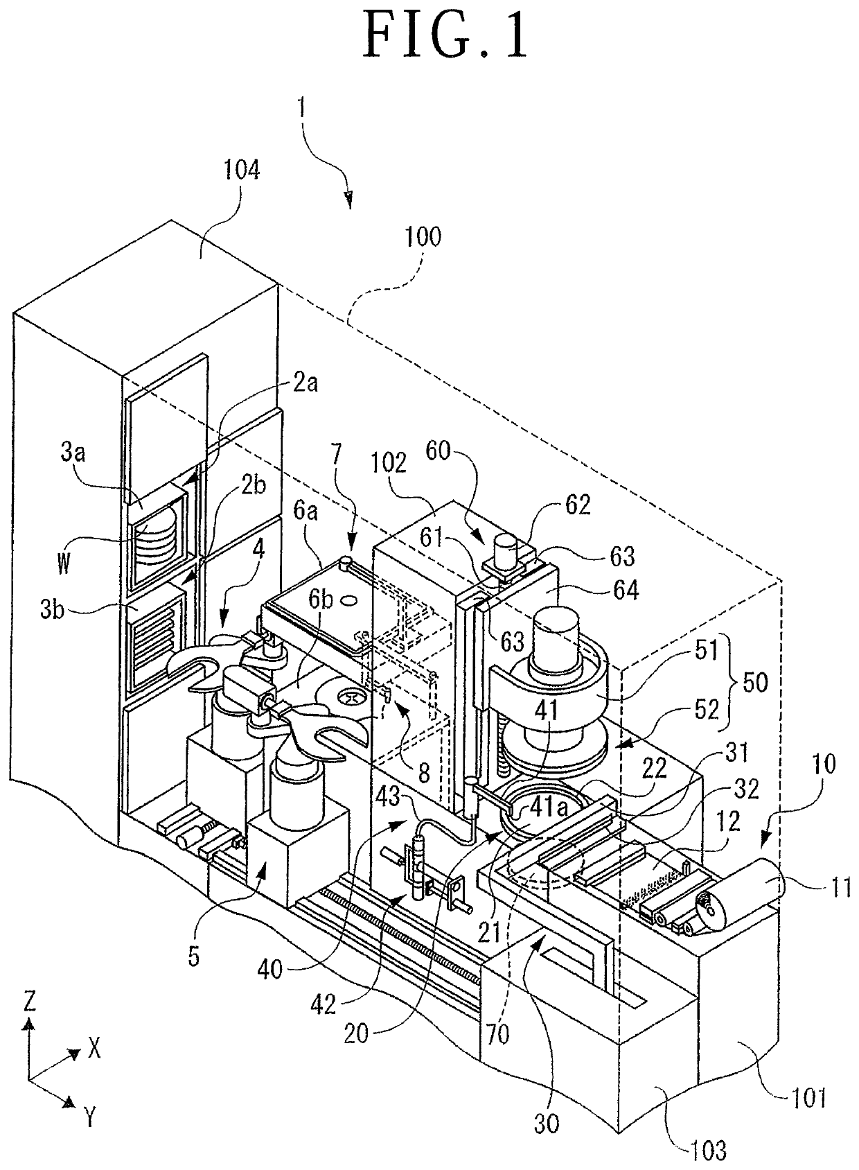
[0025]A protective member forming apparatus 1 depicted in FIG. 1 is one example of an apparatus that forms a protective member by pushing and spreading a liquid resin over the lower surface of a wafer W and curing the liquid resin. The wafer W is one example of a workpiece and is a silicon wafer with a plate shape, for example.

[0026]The protective member forming apparatus 1 includes a casing 100, an apparatus base 101 disposed in the casing 100, a column 102 disposed upright on the apparatus base 101, a support base 103 disposed adjacent to the apparatus base 101, and a cassette housing main body 104 joined to the rear end side of the casing 100.

[0027]The cassette housing main body 104 has housing spaces 2a and 2b at two stages in the upward-downward direction. A cassette 3a in which plural wafers W before the protective member is formed are housed is disposed in the housing space 2a at the upper stage. A cassette 3b in which plural wafers W on which the protective member has been f...


PUM


Abstract

A holding table for holding a wafer includes plural pins, and a wafer holding surface includes the tips of the plural pins. Therefore, small dust enters between the pins and thus is less readily left between the wafer holding surface and the wafer. Therefore, when the wafer is sucked and held, a gap is less readily made between the wafer holding surface and the wafer. Thus, the occurrence of the situation in which the wafer is held in a waving state is suppressed. For this reason, when a liquid resin is pushed to spread over the lower surface of the wafer, an air bubble enters less readily between the liquid resin and the wafer. This can suppress entry of the air bubble in a protective member obtained by curing the liquid resin.

Description

BACKGROUND OF THE INVENTIONField of the Invention[0001]The present invention relates to a protective member forming apparatus.Description of the Related Art[0002]The as-sliced wafer obtained by slicing a semiconductor ingot has undulation. A wafer is generated by removing the undulation and planarizing the as-sliced wafer. Regarding this, it is desired to remove the undulation by grinding one surface of the as-sliced wafer in the state in which the undulation has not been corrected. Thus, a protective member is formed on the other surface of the as-sliced wafer in the state in which the undulation has not been corrected, and the as-sliced wafer is held by a holding table with the intermediary of the protective member. Then, the one surface of the held as-sliced wafer is ground by a grinding abrasive. A protective member forming apparatus that forms the above-described protective member is disclosed in Japanese Patent Laid-open No. 2017-168565 and Japanese Patent Laid-open No. 2017-1...

Claims


Application Information

Patent Timeline
IPC IPC(8): H01L21/67B05C1/02H01L21/304H01L21/683H01L21/02
CPCH01L21/6836B05C1/02H01L21/304H01L21/02623H01L21/02282H01L21/02307H01L21/6715H01L21/67132B24B37/27B24B37/34H01L21/6838H01L21/68764H01L2221/68327
Inventor NAMIOKA, SHINICHI
Owner DISCO CORP
Why Eureka
Try Eureka