
System and method for reducing friction, torque and drag in artificial lift systems used in oil and gas production wells

a technology of artificial lift system and oil well, applied in the direction of machines/engines, positive displacement liquid engines, mechanical equipment, etc., can solve the problems of increased energy consumption, lost production, inefficient production, etc., and achieve the effect of reducing friction in the fluid production pump and increasing the protective barrier

Active Publication Date: 2020-02-20
RETTBERG SCOTT
View PDF0 Cites 1 Cited by
  • Summary
  • Abstract
  • Description
  • Claims
  • Application Information

AI Technical Summary

Benefits of technology

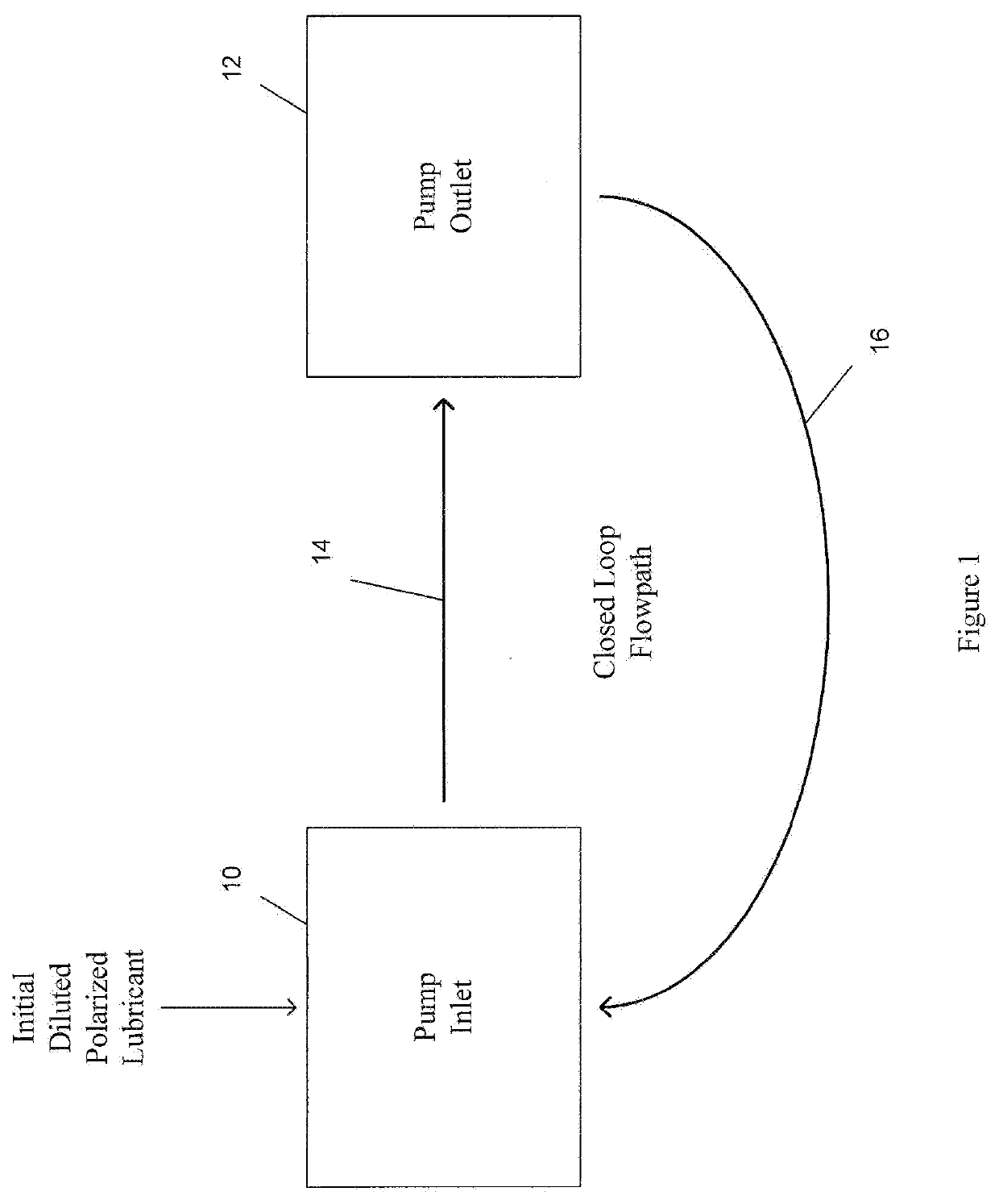
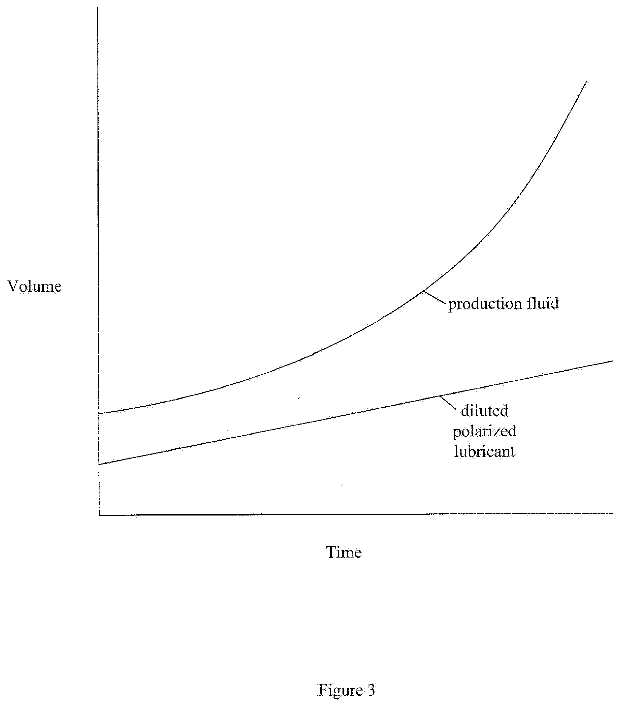
The present disclosure relates to a lubricant and a method of using it to reduce drag, friction, and torque in oil and gas producing pumps. This lubricant solution addresses the issues of wear and failure of production system components due to excessive friction, torque, and drag, which may result in reduced production volumes, increased energy consumption, and lost production related to downtime and increased energy costs of operation. The method may include filling scratches in the protective barrier with the lubricant and increasing coverage of the protective barrier on the components of the pump. The diluted lubricant may circulate through the pump and components, allowing it to be attracted to them via a positive ion charge. Overall, this lubricant solution improves pump efficiency, longevity, and performance by reducing friction, torque, and drag.

Problems solved by technology

Such pumps may include components such as sucker rods and tubing which are subject to wear during operation.
Wear may lead to inefficient production, higher energy consumption, and lost production caused by less than optimal run speeds.
Furthermore, in the event of component failure, such components may be expensive and repair and replacement may be very time consuming.
These issues may have previously stemmed from a lack of a sufficient lubricant solution for down hole oil and gas production systems which addresses performance, pump efficiency, longevity, or limited production capability due to the friction of rod-on-tubing contact points, motor torque, and drag in Artificial Lift Systems, or the problem of excessive wear and premature failure of production system components.
However, in oil production well operations, excessive friction, torque, and drag may reduce production volumes, and in some cases, cause pump inefficiencies and performance issues.
Friction, torque and / or drag may create excessive wear on components of oil production well systems, and consequently, may increase the cost of ownership and operation through premature wear, failure, replacement, and lost production related to downtime and increased energy costs of operation.
These problems may affect all major types of Artificial Lift Systems, including progressing cavity pumps, electronic submersible pumps, rod lifts or sucker-rod pumps, and various surface pumps used to move gas condensate, salt water disposal, and other fluids.

Method used


Image

  • System and method for reducing friction, torque and drag in artificial lift systems used in oil and gas production wells
  • System and method for reducing friction, torque and drag in artificial lift systems used in oil and gas production wells
  • System and method for reducing friction, torque and drag in artificial lift systems used in oil and gas production wells

Examples


Embodiment Construction

[0033]The detailed description set forth below in connection with the appended drawings is intended as a description of certain embodiments of a diluted lubricant for use with oil and gas production wells, and a related method of use, and is not intended to represent the only forms that may be developed or utilized. The description sets forth the various structure and / or functions in connection with the illustrated embodiments, but it is to be understood, however, that the same or equivalent structure and / or functions may be accomplished by different embodiments that are also intended to be encompassed within the scope of the present disclosure. It is further understood that the use of relational terms such as first and second, and the like are used solely to distinguish one entity from another without necessarily requiring or implying any actual such relationship or order between such entities.

[0034]Various aspects of the present disclosure relate to a method of creating a lubrican...


PUM

PropertyMeasurementUnit
volumeaaaaaaaaaa
volumeaaaaaaaaaa
pressureaaaaaaaaaa

Abstract

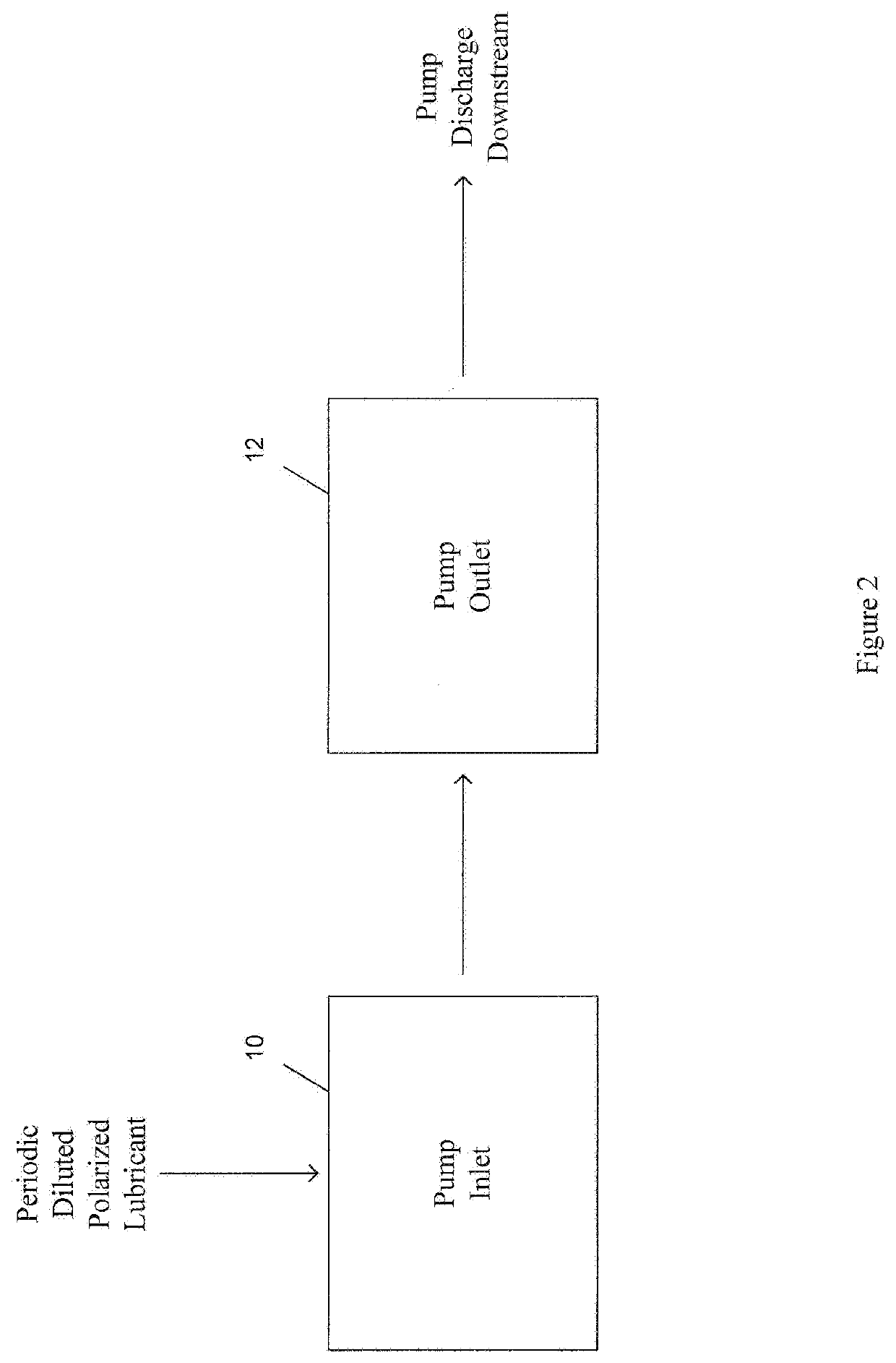
A method of lubricating a fluid production pump may include mixing a polarized lubricant with water to produce a diluted lubricant. The method may additionally include creating a flowpath within the fluid production pump. An initial volume of the diluted lubricant may be circulated within the flowpath to allow the diluted lubricant to react with components of the fluid production pump and form a protective barrier on the components of the fluid production pump. The method may further comprise repeatedly introducing a periodic volume of diluted lubricant into the fluid production pump according to a predefined lubrication schedule.

Description

CROSS-REFERENCE TO RELATED APPLICATIONS[0001]This application is a continuation application of U.S. patent application Ser. No. 15 / 880,439, filed on Jan. 25, 2018, which claims priority to U.S. Provisional Application No. 62 / 451,071, filed Jan. 27, 2017, and U.S. Provisional Application No. 62 / 581,610, filed Nov. 3, 2017, the contents of which are expressly incorporated herein by reference.STATEMENT RE: FEDERALLY SPONSORED RESEARCH / DEVELOPMENT[0002]Not ApplicableBACKGROUND1. Technical Field[0003]The present disclosure relates generally to lubrication, and more specifically to a diluted polarized lubricant and a related method of use for lubricating industrial pumps, such as pumps used for oil and gas production.2. Description of the Related Art[0004]Artificial lift systems (ALS) are commonly used to pump production fluid from oil and gas producing wells. Such lift systems tend to be inefficient which may result in higher energy consumption and lost production.[0005]Accordingly, ther...

Claims


Application Information

Patent Timeline
Patent Type & Authority Applications(United States)
IPC IPC(8): C10M105/24C10M173/00F16N15/00C10M125/14
CPCC10M2207/401C10M173/00F16N15/00C10M125/14C10M105/24F04B39/02
Inventor RETTBERG, SCOTT
Owner RETTBERG SCOTT
Learn More