Body temperature measuring device

a technology of body temperature and measuring device, which is applied in the field of body temperature measuring device, can solve the problems of inability to appropriately eliminate the influence of disturbance, delay in grasping, and difficulty in grasping heat generation or the like, so as to remove inaccurate temperature data, the influence of disturbance can be appropriately eliminated, and the effect of grasping heat generation

Active Publication Date: 2020-02-27
MURATA MFG CO LTD
View PDF0 Cites 9 Cited by
  • Summary
  • Abstract
  • Description
  • Claims
  • Application Information

AI Technical Summary

Benefits of technology

[0011]According to the body temperature measuring device of the exemplary aspect, it is determined whether or not the temperature detection section (e.g., a plurality of temperature sensors) is thermally in an equilibrium state (e.g., a state where there is no variation in thermal flow rate), and body temperature data is acquired based on temperature data detected when the temperature detection section is determined to be in a thermal equilibrium state and a thermal resistance value of the thermal resistor. For this reason, for example, even though the temperature detection section temporarily is made into a non-equilibrium state due to such as a sudden change (e.g., disturbance) in the ambient temperature with a person enter...

Problems solved by technology

Accordingly, in the above-described wearable temperature measuring device of Patent Document 1, although the body temperature is estimated by using the inverse calculation model constructed by the PLS regression analysis, there is a risk that the influence of disturbance cannot be appropriately eliminated since the function of accurately correcting (i.e., compensating) the influence of the disturbance such as t...

Method used


Image

  • Body temperature measuring device
  • Body temperature measuring device
  • Body temperature measuring device

Examples


first exemplary embodiment

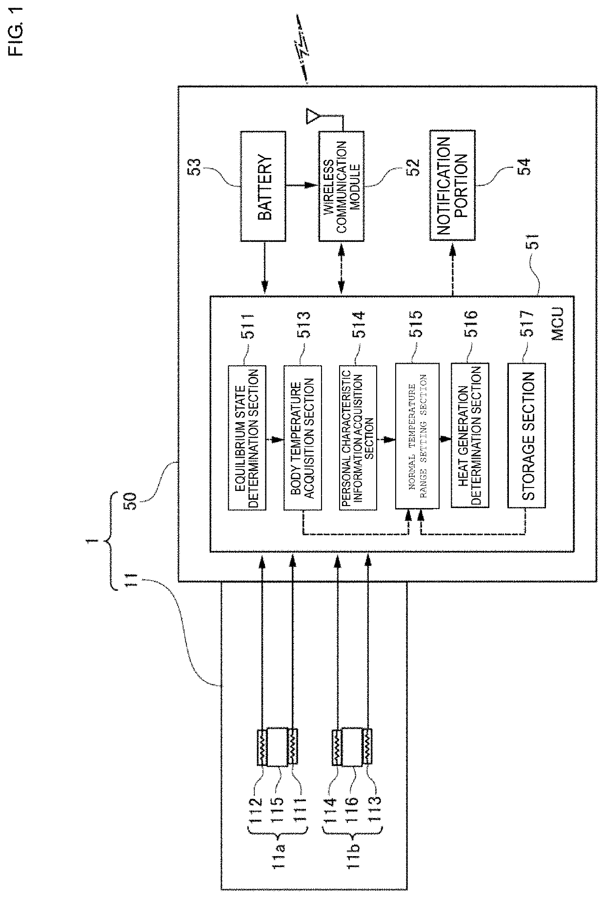
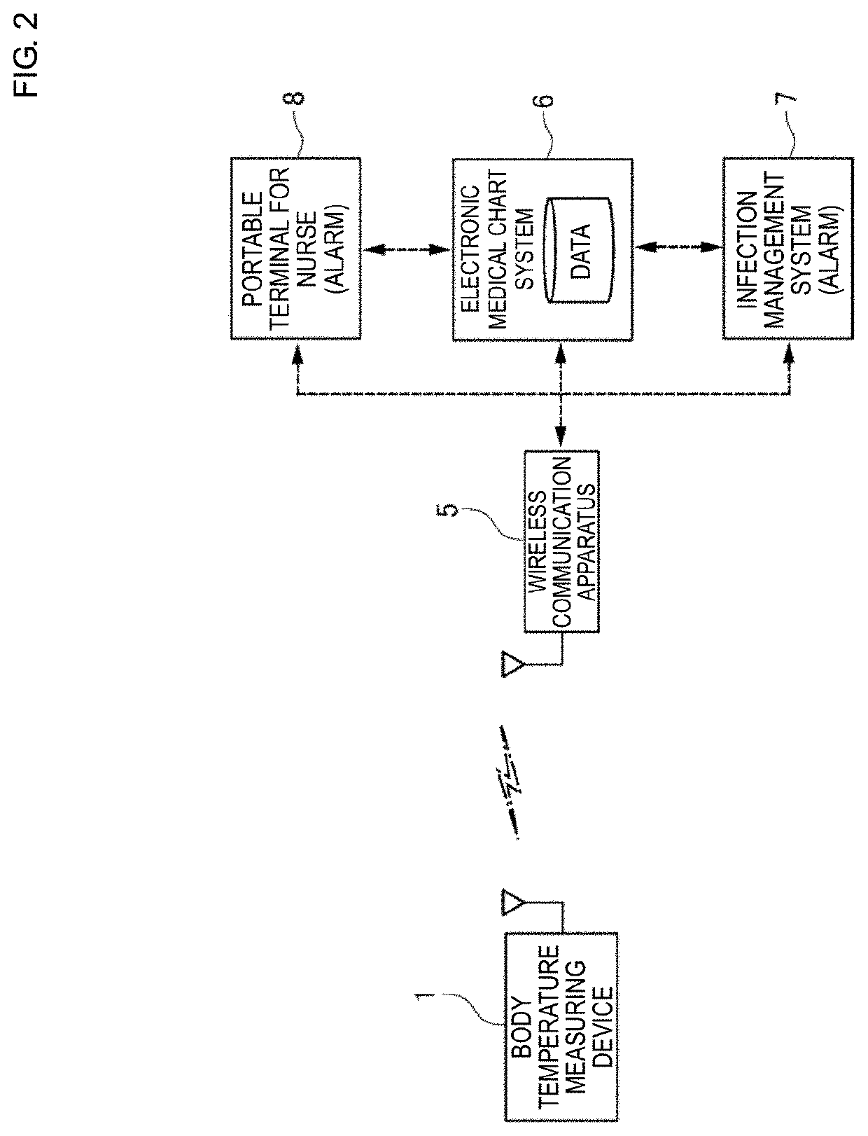
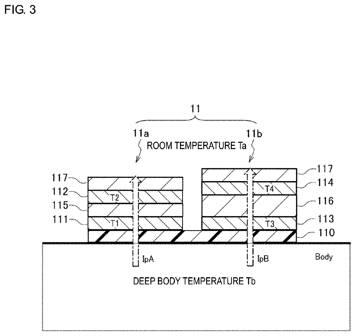
[0028]A configuration of a body temperature measuring device 1 according to a first exemplary embodiment will be described with reference to FIG. 1 to FIG. 3 together. Here, a case where the body temperature measuring device 1 is applied to, for example, an intra-hospital system (e.g., electronic medical chart system 6 and infection management system 7) will be described as an example. FIG. 1 is a block diagram illustrating a functional configuration of the body temperature measuring device 1. FIG. 2 is a block diagram illustrating an overall configuration of an intra-hospital system to which the body temperature measuring device 1 is applied. FIG. 3 is a diagram illustrating a configuration of a temperature detection section 11 constituting the body temperature measuring device 1.

[0029]In an exemplary aspect, the body temperature measuring device 1 includes the temperature detection section (simply referred to as a “temperature detector”, which can be a non-heating type deep body t...

second exemplary embodiment

[0083]Next, a body temperature measuring device 2 according to a second exemplary embodiment will be described with reference to FIG. 7 together with FIG. 8. Here, a description of the configuration of the same as or similar to that of the above-described first embodiment will be simplified or omitted, and different points will be mainly described. FIG. 7 is a block diagram illustrating a functional configuration of the body temperature measuring device 2. FIG. 8 is a block diagram illustrating an overall configuration of an intra-hospital system to which the body temperature measuring device 2 is applied. It is noted that the same reference signs are given to constituent elements which are the same as or equivalent to those in the first embodiment in FIG. 7 and FIG. 8 and the details will not be repeated herein.

[0084]The body temperature measuring device 2 is different from the body temperature measuring device 1 according to the first embodiment described above in that a temperatu...

third exemplary embodiment

[0098]Next, with reference to FIG. 13 together with FIG. 14, a description will be given of a body temperature measuring device 3 according to a third embodiment. Here, a description of the configuration of the same as or similar to that of the above-described first embodiment will be simplified or omitted, and different points will be mainly described. FIG. 13 is a block diagram illustrating a functional configuration of the body temperature measuring device 3. FIG. 14 is a block diagram illustrating an overall configuration of an intra-hospital system to which the body temperature measuring device 3 is applied. It is noted that the same reference signs are given to constituent elements which are the same as or equivalent to those in the first embodiment in FIG. 13 and FIG. 14.

[0099]The body temperature measuring device 3 is different from the body temperature measuring device 1 according to the above-described first embodiment in that a photoplethysmographic sensor 118 for detecti...


PUM


Abstract

A body temperature measuring device includes a temperature detector including a first thermal resistor and a first pair of temperature sensors that sandwich the thermal resistor and continuously detect temperature data, and a second thermal resistor and a second pair of temperature sensors that sandwich the second thermal resistor and continuously detect temperature data. Moreover, an equilibrium state determination component determines whether the temperature detector is thermally in an equilibrium state based on detected temperature data, and a body temperature acquisition component acquires body temperature data based on temperature data detected when the temperature detector is in a thermal equilibrium state and a physical property value of the thermal resistors.

Description

CROSS REFERENCE TO RELATED APPLICATIONS[0001]The present application is a continuation of PCT / JP2018 / 016535 filed Apr. 24, 2018, which claims priority to Japanese Patent Application No. 2017-088565, filed Apr. 27, 2017, the entire contents of each of which are incorporated herein by reference.TECHNICAL FIELD[0002]The present invention relates to a body temperature measuring device and, more particularly, to a body temperature measuring device for continuously a measuring body temperature (deep body temperature).BACKGROUND[0003]Currently, there are proposed techniques for measuring body temperature (i.e., deep body temperature) by continuously detecting a body surface temperature. For example, Patent Document 1 (identified below) discloses a wearable temperature measuring device for estimating a body temperature, such as an oral temperature, based on time-series body surface temperature data (for example, body surface temperature data of a subject measured during sleeping).[0004]More...

Claims


Application Information

Patent Timeline
IPC IPC(8): A61B5/01A61B5/00G01K7/16G01K13/00
CPCG01K7/16G01K13/002A61B5/01A61B5/746A61B2562/0271A61B5/0008A61B2560/0252A61B5/02055G16H50/20A61B5/7221G16H40/63G16H10/60Y02A90/10G01K7/427G01K13/20A61B5/7264
Inventor TSUCHIMOTO, HIROFUMI
Owner MURATA MFG CO LTD
Why Eureka
Try Eureka