
Method of identifying and neutralizing low-altitude unmanned aerial vehicle

a low-altitude, unmanned aerial vehicle technology, applied in the direction of reradiation, instruments, transportation and packaging, etc., can solve the problems of increasing the possibility of sporadic terrorism such as small bombs, low-intensity conflicts, and increasing the use of uavs for terrorism, so as to collect communication and sound data more accurately

Inactive Publication Date: 2020-02-27
CHOI SEUNG HEE +1
View PDF0 Cites 15 Cited by
  • Summary
  • Abstract
  • Description
  • Claims
  • Application Information

AI Technical Summary

Benefits of technology

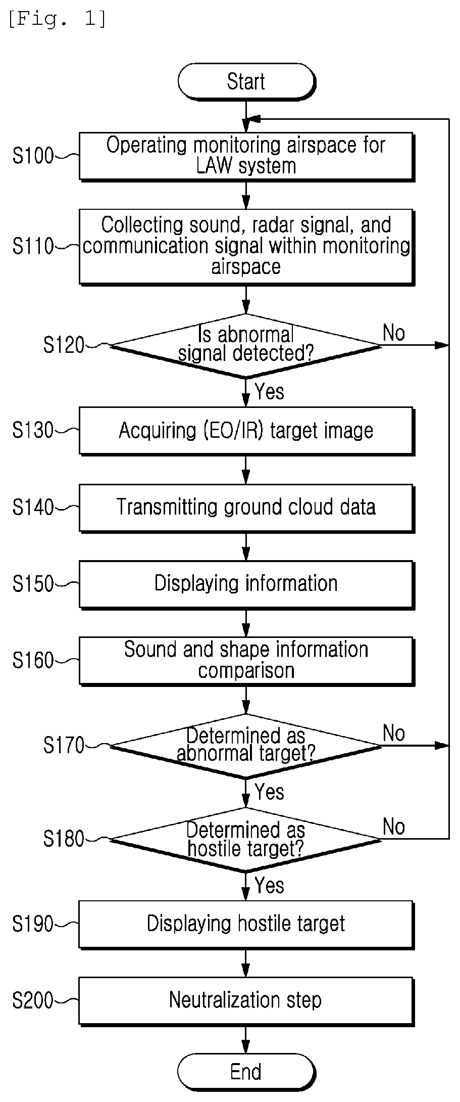
The present invention is about identifying abnormal signals using sound and shape information of UAV types. This helps overcome the limitations of conventional detectors and avoids detection blind zones in low-altitude airspace. By combining sound-based sensors, electro-optical sensors, and infrared sensors, the system can collect more accurate communication and sound data in the monitoring area. Additionally, this identification system can be used as an effective anti-aircraft weapon system capable of real-time attack when operated in conjunction with ground interceptor and attack systems.

Problems solved by technology

North Korea is constantly causing low-intensity conflicts with new forms of irregular warfare such as attempts to conduct surveillance by small unmanned aerial vehicles (UAVs) and cyber terrorism, as well as asymmetric threats such as the development of nuclear weapons and ballistic missile launch tests.
As a result, the possibility of terrorism using an UAV has also increased.
In addition, recently released hoverbike technology can easily allow access to major facilities by an unspecified number of people, thereby increasing the possibility of sporadic terrorism such as small bombs and IED terrorism.
This means that the above ground level (AGL) is also very irregular depending on the terrain, which is highly likely to degrade the detection capability due to terrain masking when operating ground-based low altitude acquisition radar.

Method used


Image

  • Method of identifying and neutralizing low-altitude unmanned aerial vehicle
  • Method of identifying and neutralizing low-altitude unmanned aerial vehicle
  • Method of identifying and neutralizing low-altitude unmanned aerial vehicle

Examples


Embodiment Construction

[0023]Advantages and features of the present invention, and methods to achieve them will be apparent from the following embodiments that will be described in detail with reference to the accompanying drawings. It should be understood that the present invention is not limited to the following embodiments and may be embodied in different ways, and that the embodiments are given to provide complete disclosure of the invention and to provide a thorough understanding of the present invention to those skilled in the art. The scope of the present invention is defined only by the claims. Throughout the description, the same reference numerals refer to same elements.

[0024]In the following description, it is to be noted that, when the functions of conventional elements and the detailed description of elements related with the present invention may make the gist of the present invention unclear, a detailed description of those elements will be omitted. Further, the terms described below are de...


PUM


Abstract

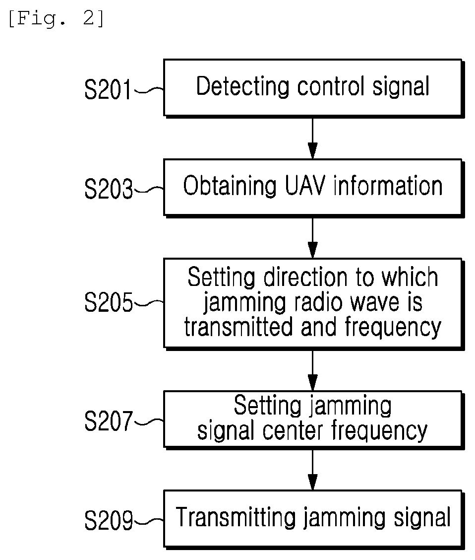
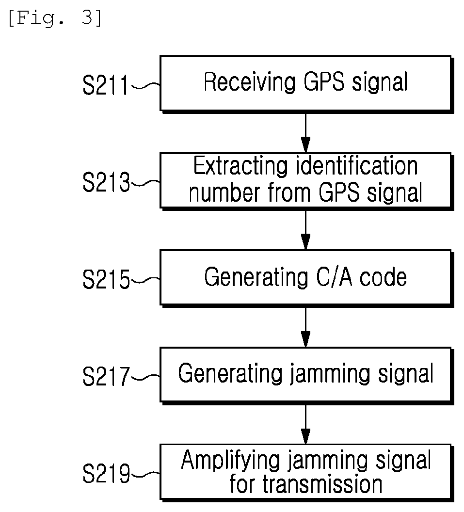
Disclosed is a method of identifying and neutralizing a low-altitude unmanned aerial vehicle. According to an embodiment, a low-altitude unmanned aerial vehicle identification system is configured to set monitoring airspace for a low altitude warning system, and to determine an abnormal signal generated in the monitoring airspace and a hostile target through low-altitude unmanned aerial vehicle identification information that contains a radar signal, an RF signal, an image signal, a sound signal, UAV shape information, and a communication signal in the set monitoring airspace. Further, correspondingly, GPS jamming, control signal jamming, gyro sensor jamming, spoofing, and the like are disclosed as neutralization methods.

Description

CROSS REFERENCE TO RELATED APPLICATION[0001]This application is based on and claims priority from Korean Patent Applications Nos. 10-2018-0097384 filed on Aug. 21, 2018 and 10-2019-0053159 filed on May 7, 2019 in the Korean Intellectual Property Office, the disclosure of which is incorporated herein in its entirety by reference.BACKGROUND OF THE INVENTIONField of the Invention[0002]The present invention relates generally to a method and a system for identifying an unmanned aerial vehicle. More particularly, the present invention relates to a method of identifying and neutralizing an unmanned aerial vehicle for low-altitude unmanned aerial vehicle identification and abnormal target determination in low-altitude airspace.[0003]Description of the Related Art[0004]Unless otherwise indicated herein, the contents set forth in this section are not prior art to the claims of this application and are not to be construed as being prior art to be included in this section.[0005]Due to the innov...

Claims


Application Information

Patent Timeline
Patent Type & Authority Applications(United States)
IPC IPC(8): G01S7/41B64C39/02B64F1/22F41H11/00H04K3/00G01S7/52
CPCB64F1/22G01S7/52017H04K3/825F41H11/00B64C39/024B64C2201/22B64C2201/145G01S7/411F41H11/02B64U70/30G01S13/867B64B1/40B64U10/30B64U2201/104B64U20/10
Inventor YOON, SUNG WOOK
Owner CHOI SEUNG HEE
Learn More