Integrated operating room lighting and patient warming system - design and components

a technology for operating room lighting and patient warming, applied in the field of components and systems, to achieve the effect of reducing clutter, reducing oi risks, and reducing oi risks

Inactive Publication Date: 2020-03-05
OPTIMUS LICENSING AG
View PDF6 Cites 2 Cited by
  • Summary
  • Abstract
  • Description
  • Claims
  • Application Information

AI Technical Summary

Benefits of technology

[0011]It is an objective of certain embodiments of the present invention to reduce OI risks in certain settings (e.g., operating rooms, emergency rooms, exam rooms, patient rooms) of healthcare environments by engineering of components and systems to be integrated and multifunctional. Components and systems of healthcare environments can be engineered to mitigate or eliminate OI risks, for example, by reducing clutter or integrating many needed functionalities into a single component. Common components and / or functionalities that are present or desirable in modern healthcare environments are, for example, organized storage of medical supplies, air flow, sterilization and sterilizability, ambient and patient lighting, and biometric tracking.
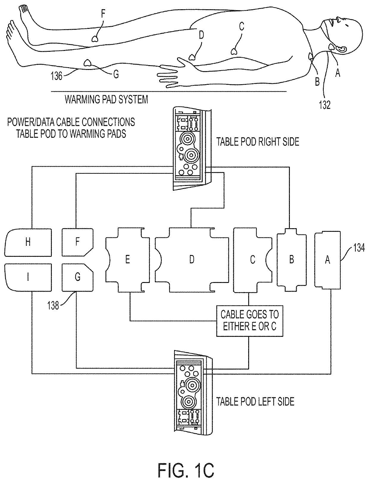
[0035]In another aspect, the present invention is directed to a patient warming pad system for alerting a user of abnormal skin surface temperature of a patient, the system comprising: one or more patient warming pads; one or more skin surface temperature sensors for monitoring the patient's skin surface temperature (e.g., by attaching the one or more skin surface temperature sensors to the patient), wherein each of the one or more skin surface temperature sensors corresponds to a respective warming pad of the one or more patient warming pads; a computing device (e.g., desktop computer, tablet, smartphone, laptop computer) comprising a processor, and a memory having instructions stored thereon, wherein the instructions, when executed by the processor, cause the processor to: display a graphic wireframe representation of portions of a patient's body and a graphical representation corresponding to each of the one or more patient warming pads showing a skin surface temperature for each of the one or more patient warming pads as measured by the corresponding at least one skin surface temperature sensors; automatically determine that the skin surface temperature for at least one of one or more patient warming pads is above or below a predetermined temperature; and at least one of: automatically alerting the user that the skin surface temperature for the at least one of the one or more patient warming pads is above or below the predetermined temperature; and automatically controlling power to the at least one of the one or more patient warming pads to decrease or increase its temperature. In certain embodiments, the graphical representation indicates a warming pad temperature for each of the one or more patient warming pads. In certain embodiments, the plurality of solid-surface sections comprise a surface made from a material with a low dielectric constant to reduce electrostatically attracted substances. In certain embodiments, the patient warming pad system comprises one or more sensors for attaching to the patient's skin in order to monitor the patient's skin temperature for a reduced likelihood of the patient developing skin burns.

Problems solved by technology

This is as opposed to the increasing number of ceiling “boom” systems that currently act as permanent spatial challenges in the modern operating room.

Method used


Image

  • Integrated operating room lighting and patient warming system - design and components
  • Integrated operating room lighting and patient warming system - design and components
  • Integrated operating room lighting and patient warming system - design and components

Examples


Embodiment Construction

[0112]It is contemplated that systems, devices, methods, and processes of the claimed invention encompass variations and adaptations developed using information from the embodiments described herein. Adaptation and / or modification of the systems, devices, methods, and processes described herein may be performed by those of ordinary skill in the relevant art.

[0113]Throughout the description, where articles, devices, and systems are described as having, including, or comprising specific components, or where processes and methods are described as having, including, or comprising specific steps, it is contemplated that, additionally, there are articles, devices, and systems of the present invention that consist essentially of, or consist of, the recited components, and that there are processes and methods according to the present invention that consist essentially of, or consist of, the recited processing steps.

[0114]It should be understood that the order of steps or order for performin...


PUM

PropertyMeasurementUnit
diameteraaaaaaaaaa
diameteraaaaaaaaaa
diameteraaaaaaaaaa

Abstract

An integrated control system for controlling components of a setting of a healthcare environment, the integrated control system including one or more wireless computing devices; one or more displays; a plurality of components of the setting, wherein at least one component of the plurality of components is an ozone sterilization system, an integrated air and lighting plenum, a surgical lighting system, a pass-through logistics cabinet, or a floor sterilization robot; and a server. The server includes a connection for connecting to a remote healthcare environment information system, and a receiver and a transmitter for communicating data between the plurality of components of the setting, medical equipment connected to one of the plurality of components, the remote healthcare environment information system, the one or more wireless computing devices and the one or more displays.

Description

RELATED APPLICATIONS[0001]This application claims the benefit of priority to U.S. Provisional Patent Application Ser. No. 62 / 419,391, filed Nov. 8, 2016, and U.S. Provisional Patent Application Ser. No. 62 / 427,773, filed Nov. 29, 2016, the contents of which are incorporated herein by reference in their entirety. This application is also related to its sister international (PCT) patent application, entitled, “Integrated Operating Room Sterilization System—Design And Components”, filed on the same date herewith, which is hereby incorporated by reference in its entirety.TECHNICAL FIELD[0002]This invention relates generally to components and systems for reducing risks to patients in healthcare environments. More particularly, in some embodiments, the invention is an integrated system that may be used in an operating room to minimize hazards that could otherwise produce complications from a surgical procedure.BACKGROUND[0003]The increasing complexity of healthcare environments with time ...

Claims


Application Information

Patent Timeline
Patent Type & Authority Applications(United States)
IPC IPC(8): A61G13/10F21V33/00F21S10/02F21S8/04F21S2/00B01L1/02A61L2/20A61G12/00A47L11/00A47B96/00
CPCA47B96/00F21S8/046A61G2210/70A61G13/108G21F7/005A61G12/002F21S10/02B01L1/02F21S2/005A61G2210/90A61L2/202F21V33/0088A47L11/00A61G13/00A61G13/10F21V33/0068F21V33/0072A61G12/00G16H40/60G16H40/20A61L2202/121A61L2202/11A61L2202/14A61L2202/25A61L2209/111A61L9/015A61F7/007A61F2007/0288A61F2007/0071A47L2201/02A47L2201/022A47L2201/024A47L2201/026A47L11/405A61G2203/46A47L11/282A47L11/4005A47L11/4061A47L11/4083A47L11/4091A47L2201/028A47L2201/04A61L2/04A61L2/10A61L2/24A61L2202/16A61L2202/17B08B3/10B08B7/0057B08B7/04B08B2203/007A61B50/10A61B2050/105A61B90/30A47L2201/00A61F7/08A61F2007/0096A61L2/088A61L2202/122A61L2202/182A61L2202/24F21S10/023F21W2131/205A61B17/00H05B3/342H05B3/56H05B3/58H05B3/52A61G13/12H04L67/12
Inventor MANGIARDI, JOHN R.
Owner OPTIMUS LICENSING AG
Why Eureka
Try Eureka