Printing apparatus with plurality of sheet feed trays
- Summary
- Abstract
- Description
- Claims
- Application Information
AI Technical Summary
Benefits of technology
Problems solved by technology
Method used
Image
Examples
first embodiment
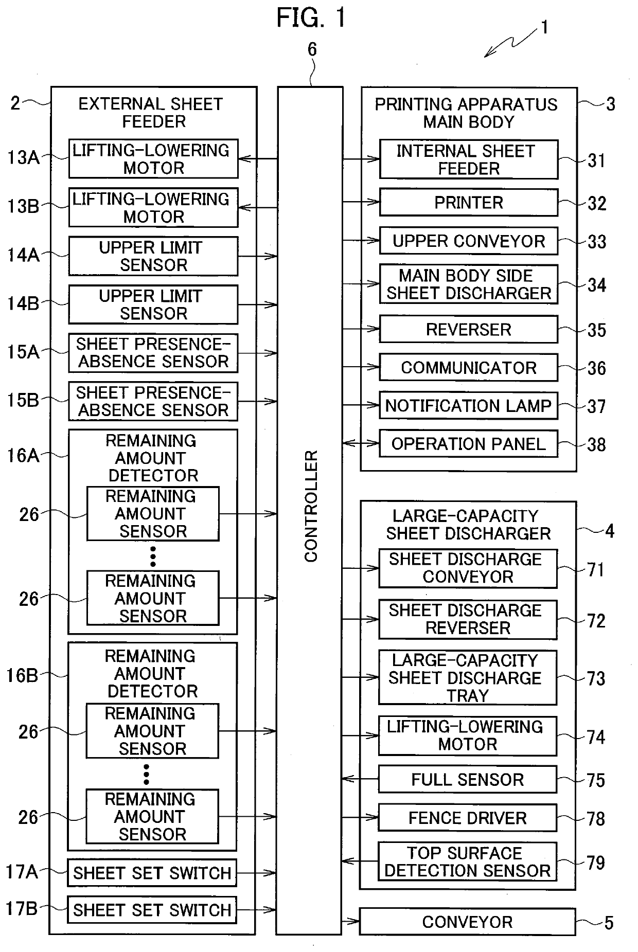
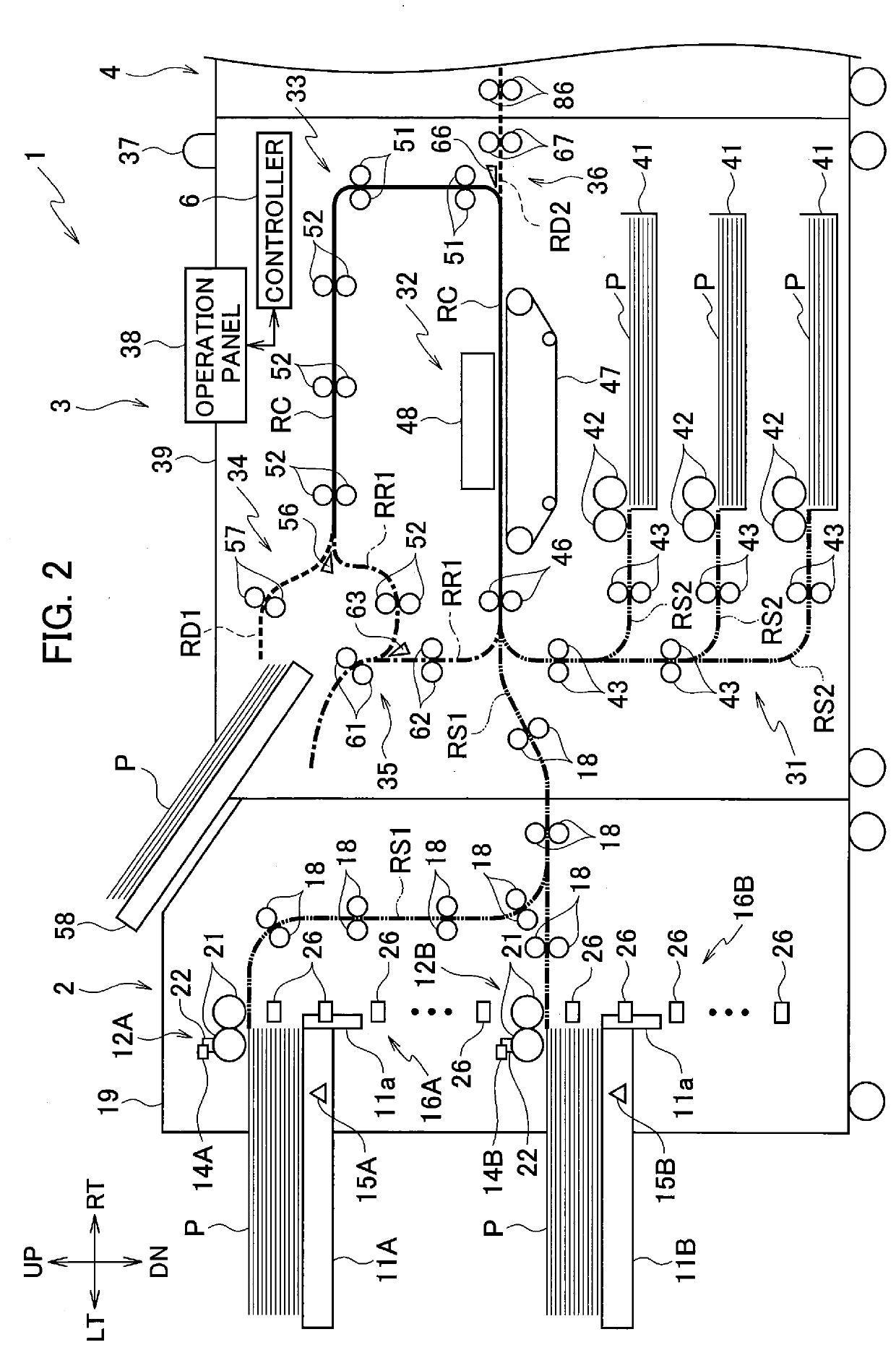
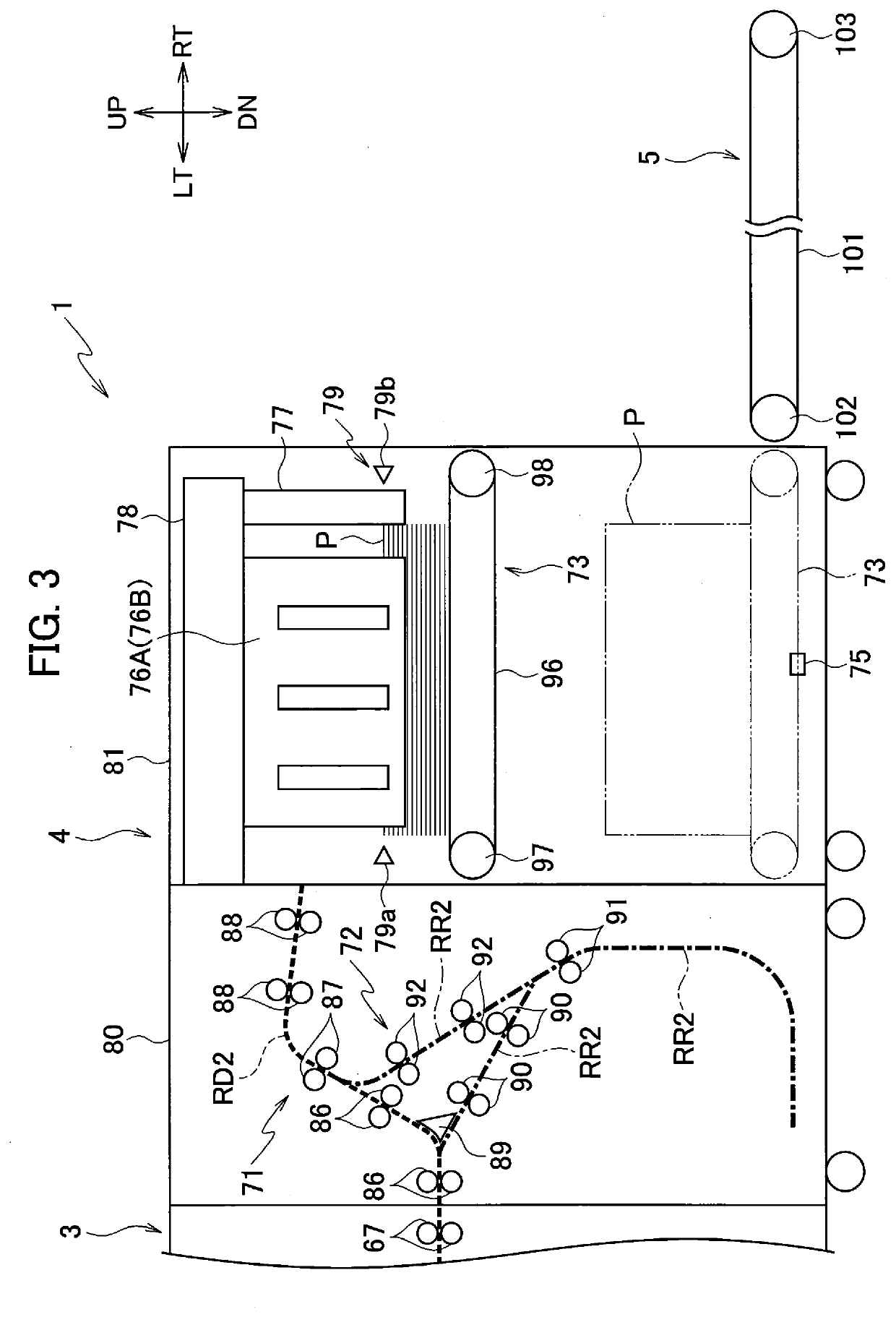
[0025]FIG. 1 is a block diagram illustrating a configuration of a printing apparatus 1 according to a FIG. 2 is a schematic configuration diagram of an external sheet feeder 2 and a printing apparatus main body 3 in the printing apparatus 1 illustrated in FIG. 1. FIG. 3 is a schematic configuration diagram of a large-capacity sheet discharger 4 and a conveyor 5 in the printing apparatus 1 illustrated in FIG. 1. In the following description, a direction orthogonal to the sheet surfaces of FIGS. 2 and 3 are referred to as front-rear direction. Moreover, up, down, left, and right in the sheet surfaces of FIGS. 2 and 3 are referred to as directions of up, down, left, and right. In FIGS. 2 and 3, the directions of right, left, up, and down are denoted by RT, LT, UP, and DN, respectively.
[0026]Routes illustrated by bold lines in FIGS. 2 and 3 are conveyance routes through which sheets P being print media are conveyed. Among the conveyance routes, a route illustrated by a solid line is a ...
second embodiment
[0151]FIG. 8 is a flowchart of the control of the external sheet feeder 2 performed in the execution of the unloading operation by the conveyor 5 in the
[0152]Processing of step S41 in FIG. 8 is the same as the processing of step S31 in FIG. 7 described in the first embodiment.
[0153]When the controller 6 determines that the unloading operation execution flag is turned on in step S41 (step S41: YES), in step S42, the controller 6 lowers one of the external sheet feed trays 11A, 11B with the smaller sheet remaining amount to the lower limit position. Note that, when the sheet remaining amounts of the external sheet feed trays 11A, 11B are included in the same range among ranges of the sheet remaining amounts detectable by the remaining amount detectors 16, the controller 6 may assume either of the external sheet feed trays 11 as the external sheet feed tray 11 with the smaller sheet remaining amount and lower this external sheet feed tray 11.
[0154]Next, in step S43, the controller 6 no...
third embodiment
[0165]FIG. 9 is a block diagram illustrating a configuration of a printing apparatus according to the FIG. 10 is a schematic configuration diagram of a large-capacity sheet discharger in the printing apparatus illustrated in FIG. 9.
[0166]As illustrated in FIGS. 9 and 10, the printing apparatus LA according to the third embodiment has a configuration in which the large-capacity sheet discharger 4 in the printing apparatus 1 of the first embodiment is replaced by a large-capacity sheet discharger 4A and the conveyor 5 is omitted. In the printing apparatus LA, the user performs work of unloading the sheets P from the large-capacity sheet discharger 4A.
[0167]The large-capacity sheet discharger 4A includes a sheet discharge conveyor 71A, a sheet discharge reverser 72, stackers 111A, 111B, a sheet discharge conveyance side case 80 housing part of the sheet discharge conveyor 71A and the like, stacker cases 112A, 112B housing the stackers 111A, 111B, respectively, and an intermediate case...
PUM
 Abstract
Description
Claims
Application Information
 - R&D
- Intellectual Property
- Life Sciences
- Materials
- Tech Scout
- Unparalleled Data Quality
- Higher Quality Content
- 60% Fewer Hallucinations
Browse by: Latest US Patents, China's latest patents, Technical Efficacy Thesaurus, Application Domain, Technology Topic, Popular Technical Reports.
© 2025 PatSnap. All rights reserved.Legal|Privacy policy|Modern Slavery Act Transparency Statement|Sitemap|About US| Contact US: help@patsnap.com


