
Method for controlling dew point of reduction furnace, and reduction furnace

Inactive Publication Date: 2016-12-15
JFE STEEL CORP
View PDF2 Cites 4 Cited by
  • Summary
  • Abstract
  • Description
  • Claims
  • Application Information

AI Technical Summary

Benefits of technology

The present invention provides a method for controlling the dew point in a reducing furnace to secure coating adhesion and perform alloying treatment without excessive temperature increase even in the case of galvanizing Si-added steel. This results in a hot-dip galvanized steel sheet with a beautiful surface appearance without decrease in productivity and high stability against disturbances such as air temperature or weather.

Problems solved by technology

However, the method described in each of Patent Literatures 1 and 2 arise a problem that there are decreases of tensile strength and ductility of a steel sheet, although coating adhesion after reduction is good, because the amount of internal oxidation is likely to be insufficient, and alloying temperature becomes 30° C. to 50° C. higher than usual under the influence of Si contained in the steel.
Therefore, it is not possible to use a method for simply increasing the amount of oxidation.
It is difficult for the method described in Patent Literature 3 to stably control a dew point within an optimum range, because when amount of water introduced into the furnace changes because of the change in the outside air temperature or the type of steel sheet, the dew point of the humidified gas is likely to be changed by this change.

Method used


Image

  • Method for controlling dew point of reduction furnace, and reduction furnace
  • Method for controlling dew point of reduction furnace, and reduction furnace
  • Method for controlling dew point of reduction furnace, and reduction furnace

Examples


example 1

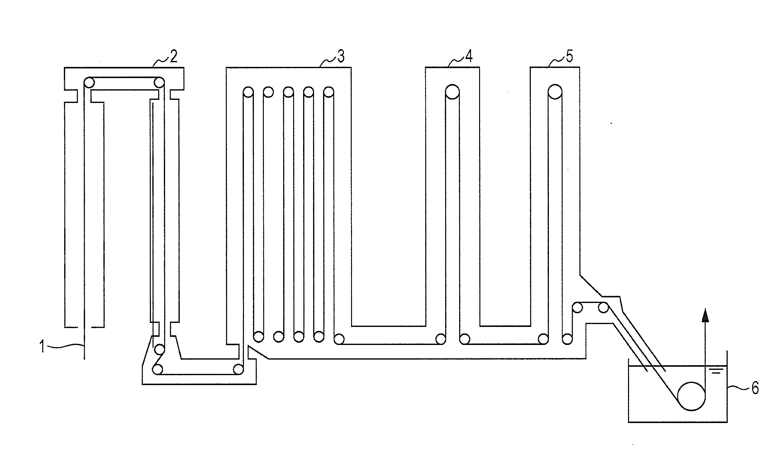
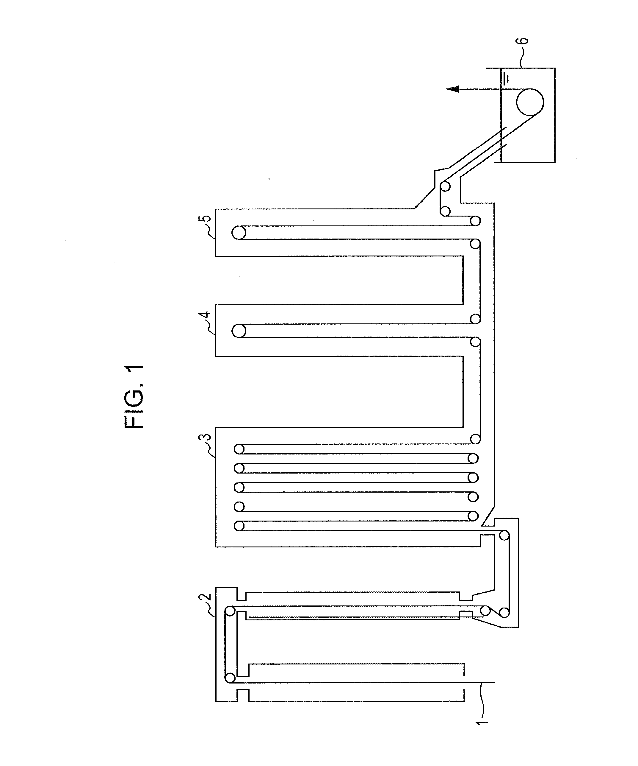
[0047]In continuous hot-dip galvanizing equipment including a direct fired furnace (DFF) type heating furnace and a radiant tube (RTF) type soaking furnace, steel sheets having the compositions shown in Table 1 were subjected to annealing and hot-dip galvanizing treatment. Subsequently, by performing alloying treatment, hot-dip galvannealed steel sheets were produced.

[0048]In the heating furnace, a DFF in which heating burners were divided into four groups (#1 to #4) was used. The three groups (#1 to #3) at the upstream side in the steel sheet travelling direction (first stage) were defined as an oxidation zone, and the final zone (#4) (second stage) was defined as a reduction zone. The air ratio in each of the oxidation zone and the reduction zone was individually controlled. Note that the length of each zone was 4 m.

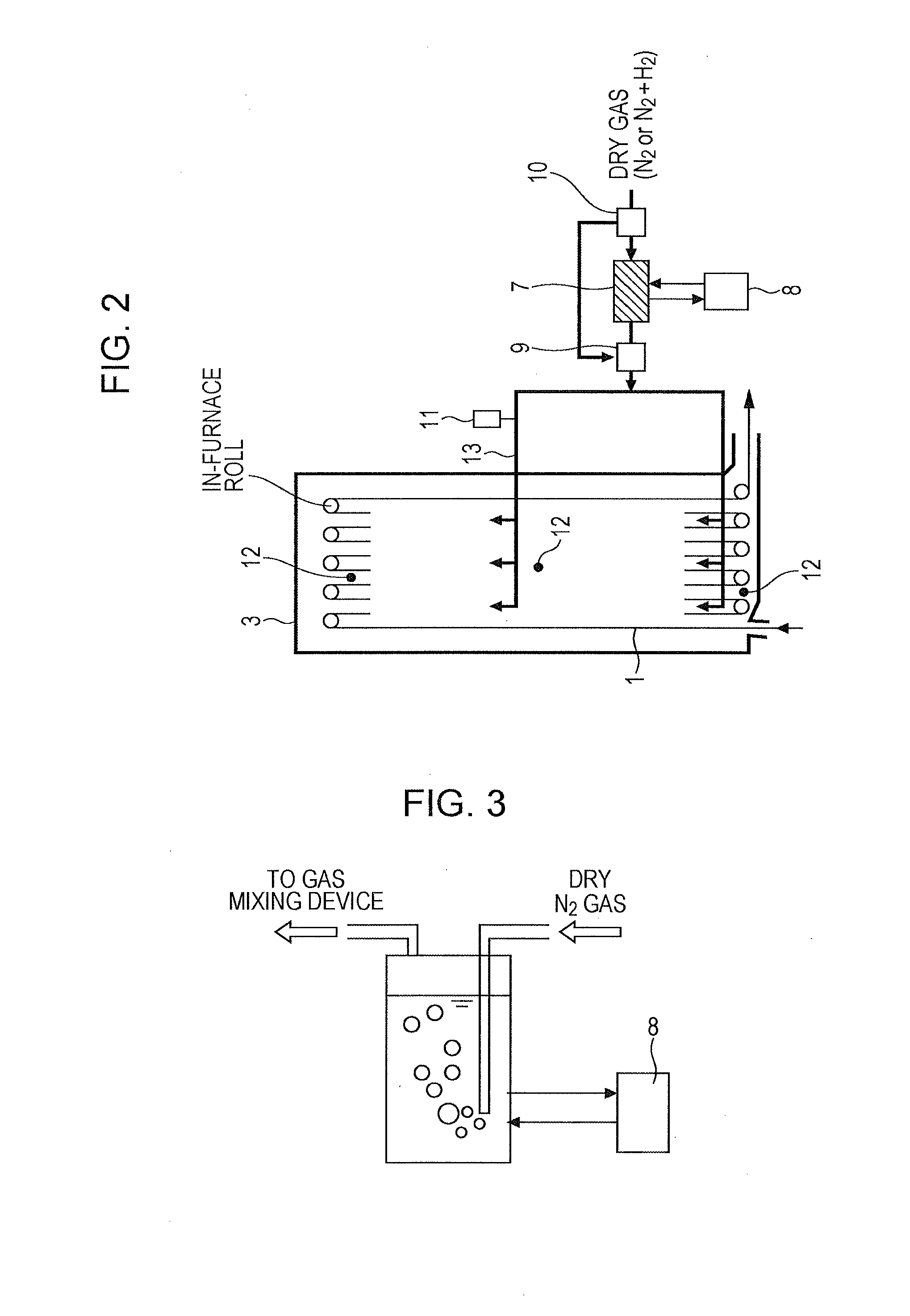
[0049]As a soaking furnace, the reducing furnace shown in FIG. 2 was used. The humidifying device was a polyimide hollow fiber membrane-type humidifying device. As sho...


PUM

PropertyMeasurementUnit
Dew pointaaaaaaaaaa
Dew pointaaaaaaaaaa
Temperatureaaaaaaaaaa

Abstract

Provided are a method for controlling a dew point in a reducing furnace and a reducing furnace in which, even in the case of galvanizing Si-added steel, coating adhesion can be secured, alloying treatment can be performed without increasing the alloying temperature excessively, and it is possible to obtain a hot-dip galvanized steel sheet having an excellent coating appearance. When a steel sheet is subjected to annealing and hot-dip galvanizing treatment using continuous hot-dip galvanizing equipment including at least a radiant tube-type reducing furnace, a mixed gas of a dry gas and a humidified gas by a humidifying device having a water vapor permeable membrane is used as a gas to be supplied into the reducing furnace. The mixed gas is supplied into the reducing furnace, thereby controlling the dew point in the reducing furnace.

Description

CROSS-REFERENCE TO RELATED APPLICATIONS[0001]This is the U.S. National Phase application of PCT / JP2015 / 000742, filed Feb. 18, 2015, which claims priority to Japanese Patent Application No. 2014-034270, filed Feb. 25, 2014, the disclosures of each of these applications being incorporated herein by reference in their entireties for all purposes.FIELD OF THE INVENTION[0002]The present invention relates to a method for controlling the dew point in a reducing furnace, and a reducing furnace.BACKGROUND OF THE INVENTION[0003]In recent years, there has been an increase in the demand for high-tensile strength steel sheets (high-tensile strength steel) that can be used, for example, to reduce weight of structures in the fields of automobiles, home electrical appliances, building materials, and the like. Regarding the high-tensile strength steel, it is known that it is possible to obtain steel sheets which have good hole expandability, for example, by incorporating Si into steel, and steel she...

Claims


Application Information

Patent Timeline
IPC IPC(8): F27D7/02C23C2/40C21D9/00C21D9/46C21D1/26C23C2/06C23C2/28
CPCF27D7/02C23C2/06C23C2/40F27D2019/0028C21D9/46C21D1/26C21D9/0012C23C2/28C21D9/561C21D1/76C23C2/0222C23C2/0038C23C2/0224C23C2/022F27B9/28F27B9/045
Inventor TAKEDA, GENTAROTAKAHASHI, HIDEYUKIMIYAKE, MASARUMAKIMIZU, YOICHISUZUKI, YOSHITSUGU
Owner JFE STEEL CORP
Learn More