Control system of miller cycle engine and method of controlling miller cycle engine

a control system and miller cycle technology, applied in electrical control, machines/engines, non-mechanical valves, etc., can solve problems such as combustion deterioration, and achieve the effect of reducing pressur

Active Publication Date: 2020-03-05
TOYOTA JIDOSHA KK
View PDF0 Cites 4 Cited by
  • Summary
  • Abstract
  • Description
  • Claims
  • Application Information

AI Technical Summary

Benefits of technology

[0005]The disclosure provides a control system of a Miller cycle engine and a method of controlling the Miller cycle engine, which can establish a decompression mode without requiring enlargement of a valve recess, in a Miller cycle engine that is operable in an early closing Miller cycle operating mode, using a variable valve mechanism of a fixed operation angle type.
[0014]According to the above configuration, the decompression mode utilizing late closing of the intake valve is implemented, in the Miller cycle engine that is operable in the early closing Miller cycle operating mode by using the variable valve mechanism of the fixed operation angle type. The late closing amount for use in the decompression mode is larger than the early closing amount at the time when the closing timing of the intake valve is most advanced (advanced to the earliest timing) by the variable valve mechanism. By executing the decompression mode with the late closing amount, it is possible to perform decompression that provides a higher pressure reduction effect than that at the time of use of the early closing amount when the closing timing is most advanced, without requiring enlargement of a valve recess. Thus, even when a mechanism of a variable operation angle type is not provided, both the early closing Miller cycle operating mode and the decompression mode can be established, without incurring an adverse effect due to enlargement of the valve recess.

Problems solved by technology

However, the enlargement of the valve recess may result in combustion deterioration due to reduction of turbulence of in-cylinder gas, for example.

Method used


Image

  • Control system of miller cycle engine and method of controlling miller cycle engine
  • Control system of miller cycle engine and method of controlling miller cycle engine
  • Control system of miller cycle engine and method of controlling miller cycle engine

Examples


first embodiment

1. First Embodiment

[0028]Referring initially to FIG. 1 through FIG. 8, a first embodiment of the disclosure will be described.

1-1. System Configuration

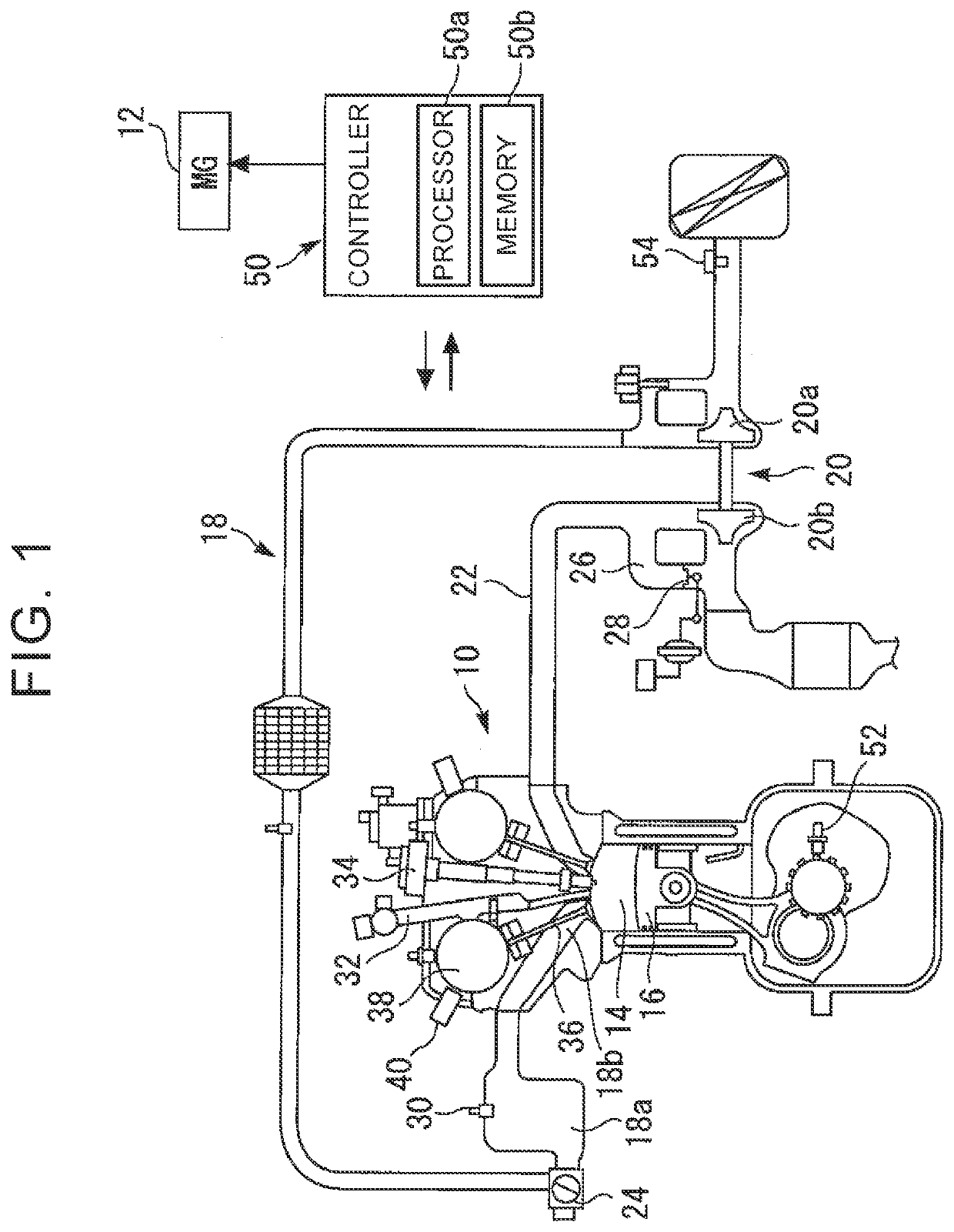
[0029]FIG. 1 illustrates the configuration of a system according to the first embodiment. The system shown in FIG. 1 includes a spark ignition internal combustion engine (e.g., gasoline engine) 10, as one example. A vehicle on which the internal combustion engine 10 is installed is, for example, a hybrid vehicle including the internal combustion engine 10 and a motor generator (MG) 12 as power sources.

[0030]A piston 16 is placed in each cylinder 14 of the internal combustion engine 10. The piston 16 reciprocates within the cylinder 14. The internal combustion engine 10 is a supercharged engine, for example, and a compressor 20a of a turbocharger 20 is placed in the intake passage 18. The compressor 20a is driven and rotated by a turbine 20b placed in an exhaust passage 22. An electronically controlled throttle valve 24 is placed downs...

second embodiment

2. Second Embodiment

[0080]Referring to FIG. 9 through FIG. 11, a second embodiment of the disclosure will be described. In the following description, the configuration shown in FIG. 1 is supposed to be used, as one example of the hardware configuration of a system according to the second embodiment.

2-1. Summary of Intake Valve Timing Control of Second Embodiment

[0081]FIG. 9 shows setting and control range of the closing timing IVC used in the intake valve timing control of the second embodiment. In this embodiment, the “early closing mode” is basically implemented in the same manner as in the first embodiment, during engine operation. However, in a given high output region located on the high-load high-rotational-speed side, a “high intake efficiency mode” as described below is implemented, in place of the “early closing mode”.

[0082]FIG. 10 shows the relationship between the intake efficiency (intake-air charging efficiency) of the internal combustion engine 10 and the closing timin...


PUM


Abstract

A control system of a Miller cycle engine includes an ECU. The ECU executes an early closing Miller cycle operating mode in which a variable valve mechanism is controlled to close an intake valve before an intake bottom dead center. The ECU executes a decompression mode in which the variable valve mechanism is controlled to close the intake valve at a point later than the intake BDC, when the engine is started. The electronic control unit executes the early closing Miller cycle operating mode after completion of the decompression mode. A later closing amount of the intake valve relative to the intake BDC, for use in the decompression mode, is larger than an early closing amount of the intake valve relative to the intake BDC when the closing timing of the intake valve is most advanced.

Description

INCORPORATION BY REFERENCE[0001]The disclosure of Japanese Patent Application No. 2018-165259 filed on Sep. 4, 2018 including the specification, drawings and abstract is incorporated herein by reference in its entirety.BACKGROUND1. Technical Field[0002]The disclosure relates to a Miller cycle engine, and more specifically relates to a control system of the Miller cycle engine, which implements an early closing Miller cycle operating mode, using a variable valve mechanism that makes the opening and closing timing of an intake valve variable while fixing the operation angle of the intake valve. The disclosure also relates to a method of controlling the Miller cycle engine.2. Description of Related Art[0003]For example, Japanese Unexamined Patent Application Publication No. 2002-061522 (JP 2002-061522 A) discloses a control system of an internal combustion engine including a variable valve mechanism (which will also be simply called “variable operation angle type mechanism”) having a f...

Claims


Application Information

Patent Timeline
Patent Type & Authority Applications(United States)
IPC IPC(8): F02D13/02
CPCF02D13/0257F02D13/023F02D13/0223F02D13/0276F02D13/0269F02D13/0238F01L1/3442Y02T10/12F02D13/0234F02D41/062F02D41/0002F02D2041/002F02D2200/0406F01L9/22F01L9/20
Inventor HOTTA, SHINTAROSADAKANE, SHINJITAKAMIYA, FUMIOHOJO, AKIRAUMEHARA, KOHEI
Owner TOYOTA JIDOSHA KK
Why Eureka
Try Eureka