Supercharge Your Innovation With Domain-Expert AI Agents!

Method For Manufacturing A Fuselage Component For An Aircraft, Fuselage Component For An Aircraft And Aircraft

a technology for fuselage components and aircraft, applied in the direction of additive manufacturing processes, manufacturing tools, other domestic articles, etc., can solve the problems of high mechanical rigidity of the stiffening structure, increase the overall manufacturing cost, and reduce the overall manufacturing cost. , to achieve the effect of high mechanical strength and efficient performan

Active Publication Date: 2020-03-12
AIRBUS OPERATIONS GMBH
View PDF0 Cites 2 Cited by
  • Summary
  • Abstract
  • Description
  • Claims
  • Application Information

AI Technical Summary

Benefits of technology

The present invention provides an improved method for making a fuselage component that is strong and efficient. This helps to make the component more durable and reliable.

Problems solved by technology

This leads to a high mechanical rigidity of the stiffening structure.
The build-up of the individual stiffening profiles directly on the surface of the shell part speeds up the process and reduces the overall manufacturing outlay.

Method used


Image

  • Method For Manufacturing A Fuselage Component For An Aircraft, Fuselage Component For An Aircraft And Aircraft
  • Method For Manufacturing A Fuselage Component For An Aircraft, Fuselage Component For An Aircraft And Aircraft
  • Method For Manufacturing A Fuselage Component For An Aircraft, Fuselage Component For An Aircraft And Aircraft

Examples


Embodiment Construction

[0035]FIG. 11 by way of example shows an aircraft 200, which comprises a fuselage 210, wings 220 extending out therefrom, an elevator assembly 230 arranged at one end of the fuselage 210 and a tailfin assembly 240 likewise arranged at the end of the fuselage 210. The fuselage 210 is of tubular construction and defines an aircraft longitudinal axis L200. An outer skin 211 of the fuselage 210 is formed by fuselage components 100, which are arranged contiguous with one another in a circumferential direction of the fuselage 210.

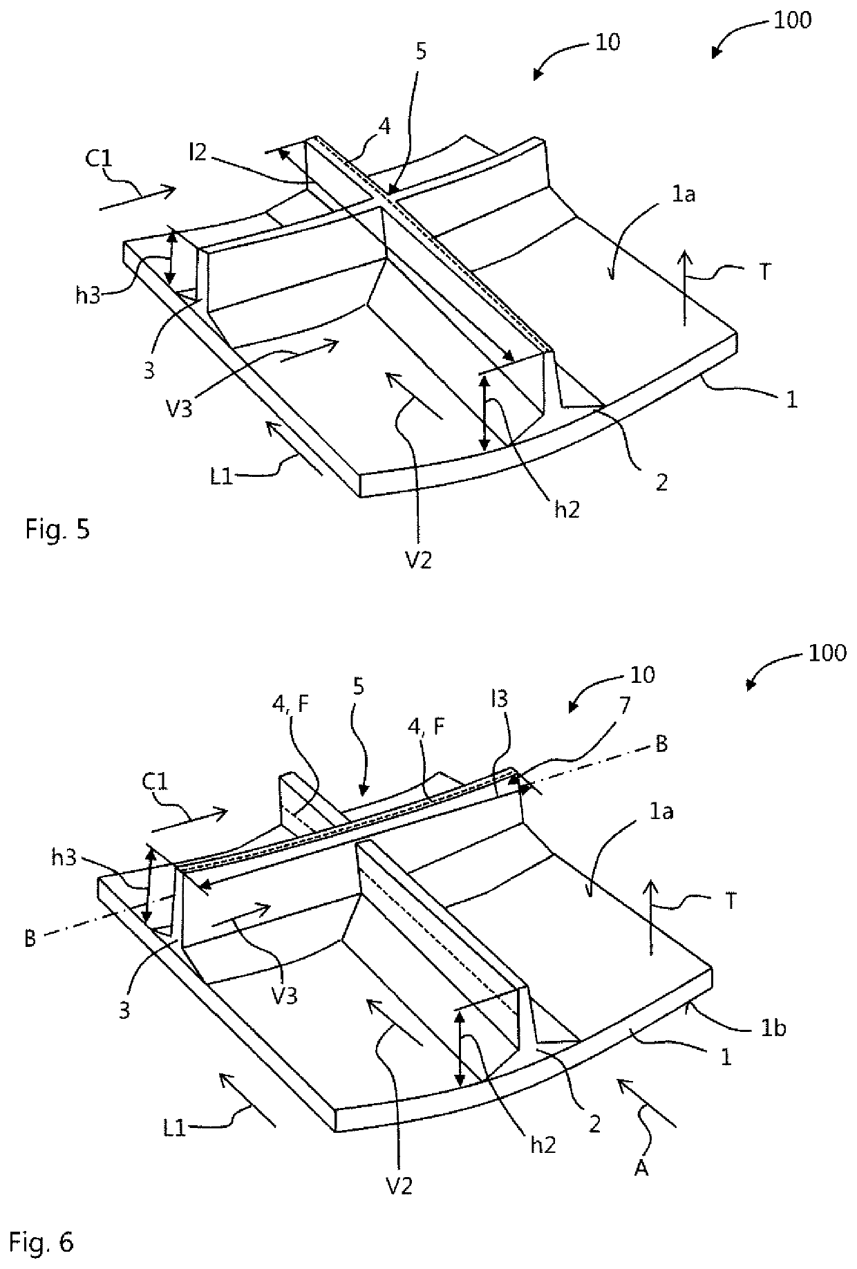
[0036]FIG. 6 by way of example shows a fuselage component 100. This comprises a shell part 1 and a stiffening structure 10 having at least a first stiffening profile 2 and at least a second stiffening profile 3.

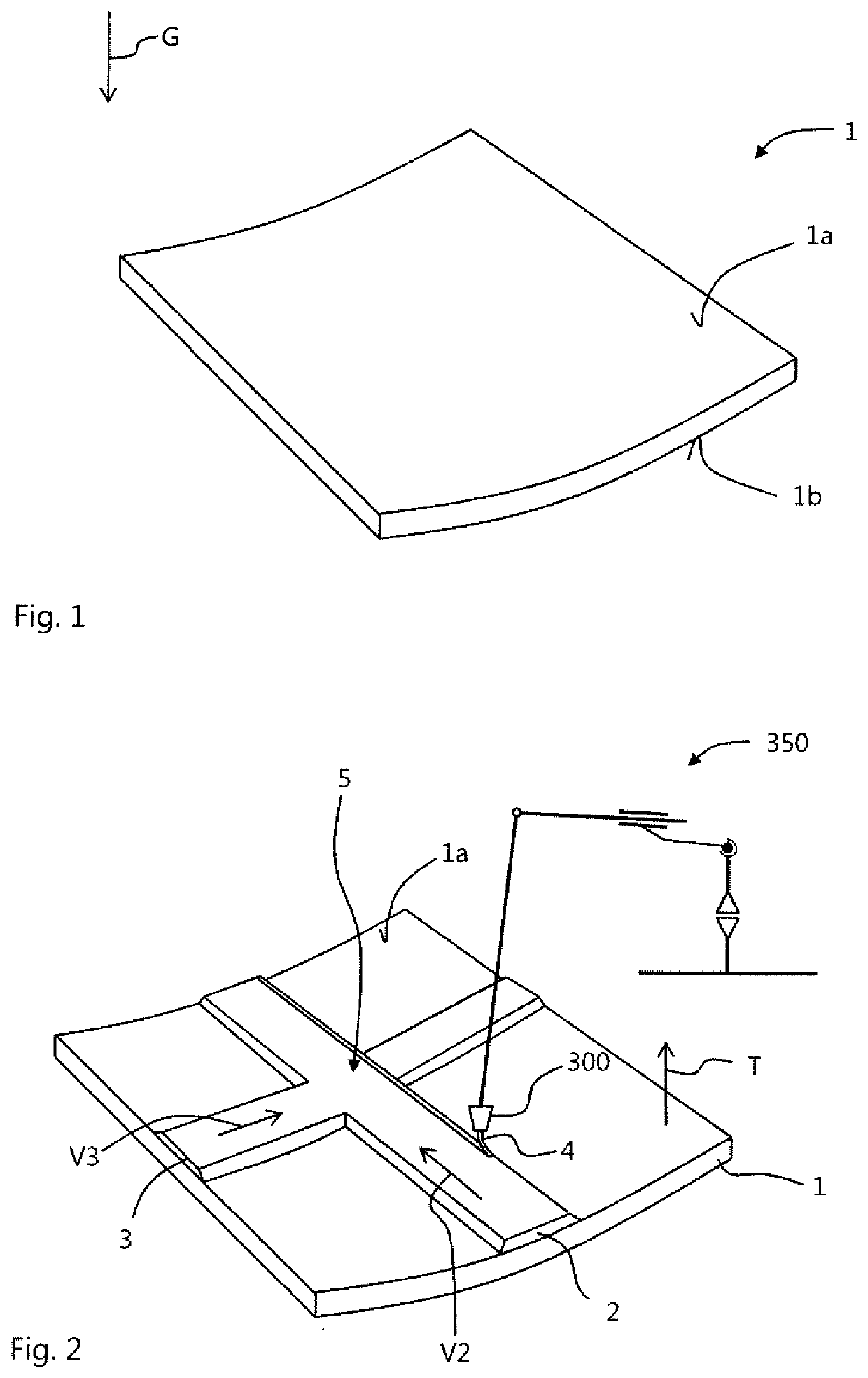
[0037]As is represented schematically in FIG. 6, the shell part 1 is formed as a two-dimensional component. The shell part 1 may, in particular, be formed as an arched body. Here an “arched body” is generally taken to mean a body or a component which has a...


PUM

PropertyMeasurementUnit
Thicknessaaaaaaaaaa
Pressureaaaaaaaaaa
Heightaaaaaaaaaa

Abstract

A method for manufacturing a fuselage component for an aircraft includes building up, on a surface of a two-dimensional shell part composed of a fibre composite material, stiffening profiles crossing at an intersection from a plurality of layers, superimposed on one another in a thickness direction, which are each formed by applying filaments, which each comprise a fibre bundle embedded in a thermoplastic material. Stabilising layers, within which the filaments extend beyond the intersection, are formed from the filaments in each of the stiffening profiles. A fuselage component and an aircraft, which comprises at least one such fuselage component, are furthermore described.

Description

FIELD OF THE INVENTION[0001]The present invention relates to a method for manufacturing a fuselage component for an aircraft, a fuselage component for an aircraft and an aircraft.BACKGROUND OF THE INVENTION[0002]Shell-shaped components composed of a fibre composite material are often used for the manufacture of a fuselage structure of an aircraft. These components typically comprise a two-dimensional shell part or skin element together with stiffening profiles, which are connected to the shell part and form a latticed stiffening structure. Here both the shell part and also the stiffening profiles are mostly formed from a fibre composite material.[0003]For manufacturing such components DE 10 2009 057 006 A1 proposes a method in which strip elements of a fibrous material are laid in grooves formed on a mould part, the grooves running in a pattern corresponding to a latticed form of the stiffening structure to be produced. The respective strip elements terminate at groove intersections...

Claims


Application Information

Patent Timeline
IPC IPC(8): B29C64/165B33Y10/00B33Y80/00B33Y70/00
CPCB33Y80/00B33Y10/00B29L2031/3082B29C64/165B33Y70/00B29K2101/12B29C64/118B29C70/38Y02T50/40B33Y70/10
Inventor LINDE, PETERHELTSCH, NORBERT
Owner AIRBUS OPERATIONS GMBH
Features
  • R&D
  • Intellectual Property
  • Life Sciences
  • Materials
  • Tech Scout
  • Unparalleled Data Quality
  • Higher Quality Content
  • 60% Fewer Hallucinations
Learn More