Replica optical element

Inactive Publication Date: 2020-03-12
SHIMADZU CORP
View PDF0 Cites 1 Cited by
  • Summary
  • Abstract
  • Description
  • Claims
  • Application Information

AI Technical Summary

Benefits of technology

[0014]As set forth above, with respect to the replica optical element of the present invention, the vertical reflectivity R meets the formula (1), so that the reflection light and the scattering light decrease and as a result, the stray light also decreases. In addition, the spectrograph using such a replica optical element improves the analytical precision and the analytical sensitivity and particularly, the analytical precision relative to the short wavelength region such as soft X-ray largely improves with contribution thereof.
[0015]In addition, the plane roughness S of the undersurface of the glass substrate relative to the replica optical element of the present invention may meet the following formula (2).
[0016]With respect to the replica optical element of the present invention, the plane roughness S meets the formula (2), so that the reflection light and the scattering light decrease and as a result, the stray light also decreas

Problems solved by technology

Whereas an absorption intensity of an incident monochromatic light, of which wavelength is separated by the replica transmissive diffraction grating, into a sample is measured when a sample is analyzed using a spectrum mode of the spectrograph, but given light having a wavelength other than the monochromatic light, i.e., stray light, contaminates the incidence, such contamination as a noise is a factor that deteriorates the analytical sensitivity

Method used


Image

  • Replica optical element
  • Replica optical element
  • Replica optical element

Examples


embodiment 1

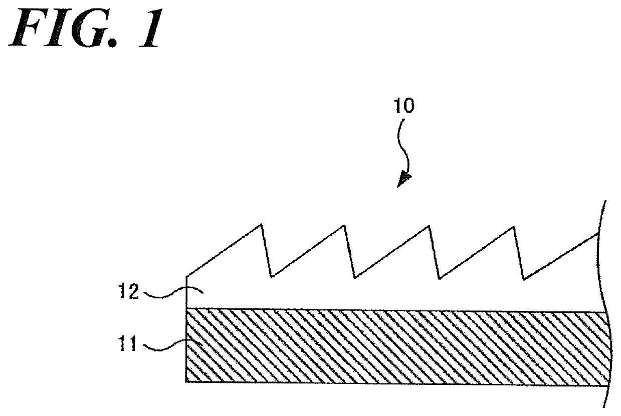
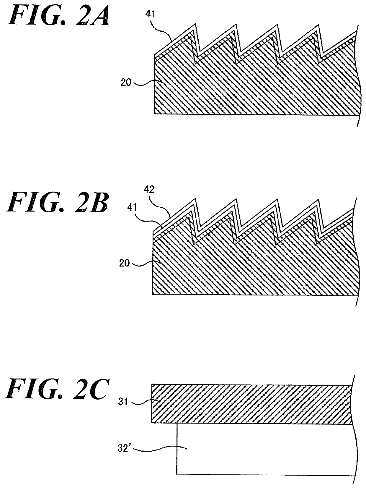
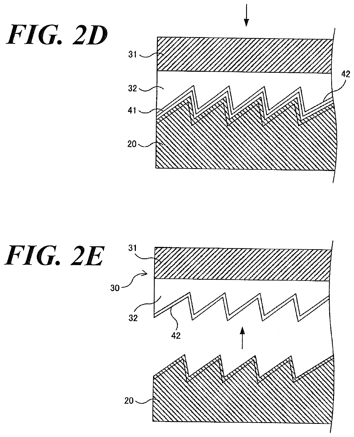
[0085]According to the manufacturing method as set forth above, the replica transmissive diffraction grating, according to the aspect of the Embodiment 1, comprising the serrate grating surface having 200 / mm grooves and blaze angle 8.6° is prepared using a flat plane replica substrate (N-SK11 a brand and a type of material available from the Schott Japan Corporation) having 11 mm thickness, 60 mm length from front to rear, and 60 mm width from right to left, of which plane roughness S is 1 nm Rms, the refractive index n1 of the material is 1.562 (D-line), and using the adhesive resin having the refractive index n2 of the adhesive resin that is 1.56 (D-line). In addition, the vertical reflectivity R is 4×10⁻⁷.

embodiment 2

[0086]The replica transmissive diffraction grating, according to the aspect of the Embodiment 2, is prepared as well as the Embodiment 1, but the replica substrate having 14 μm Rms of the plane roughness S instead of the replica substrate having 1 nm Rms of the plane roughness S. In addition, the vertical reflectivity R is 4×10⁻⁷.


PUM


Abstract

A replica optical element reduces stray light and is manufactured by the method comprising steps of: forming a mold-releasing agent film, forming a metal film, adhering, by which a top-surface of the metal film and an undersurface of a glass substrate, preparing a reflection optical element, removing the glass substrate from a mold 30 and, if a refractive index relative to D-line of the glass is n1 and a refractive index relative to D-line of the adhesive resin is n2, then a vertical reflectivity R meets a following formula (1).
R=(n1−n2)2/(n1+n2)2≤1.0×10−5  (1).

Description

CROSS REFERENCE TO RELATED APPLICATIONS[0001]This application relates to, but does not claim priority from, JP 2016-050411 filed Mar. 15, 2016 which was published as JP 2017-167231 on Sep. 21, 2017, the entire contents of which are incorporated herein by reference.FIGURE SELECTED FOR PUBLICATION[0002]FIG. 1BACKGROUND OF THE INVENTIONField of the Invention[0003]The present invention relates to a replica optical element applied to a variety of optical instruments, such as a spectrophotometer and particularly, relates to a replica diffraction grating that is mounted in a spectrograph in which a setting angle thereof is fixed.Description of the Related Art[0004]Conventionally, when a diffraction grating is subject to a mass production, a method by which a replica diffraction grating is produced using a master diffraction grating (White and Fraser Replication Method) (e.g., Patent Document 1).[0005]According to the White and Fraser replication method (e.g., refer to U.S. Pat. No. 2,464,7...

Claims


Application Information

Patent Timeline
IPC IPC(8): G02B5/18
CPCG02B5/1852G02B2005/1804G02B5/1861
Inventor KURAMOTO, SATOSHISASAI, HIROYUKI
Owner SHIMADZU CORP
Why Eureka
Try Eureka