A device and a method for non-destructively characterizing a material

a non-destructive characterization and material technology, applied in measurement devices, mechanical vibration separation, instruments, etc., can solve the problems of limited solution, inability to use elements, and inability to meet the requirements of all transducers, so as to reduce the number of emitter/receiver cells, reduce the overall size, and improve the accuracy of measurement

Active Publication Date: 2020-03-19
SAFRAN
View PDF0 Cites 0 Cited by
  • Summary
  • Abstract
  • Description
  • Claims
  • Application Information

AI Technical Summary

Benefits of technology

[0014]Advantageously, the ring of the non-destructive characterization device is hollow in its center, i.e. without any emitter / receiver cells. It is thus possible to place the ring in contact with or around the material for characterizing. In addition, the emitter / receiver cells of such a device can be selected individually and controlled to switch into an emit mode or into a receive mode. It thus becomes possible to use the ring of the device to perform either sequentially or else in combination both a radial scan and also a scan turning around the material for characterizing. The material can thus be characterized in any angular direction without moving the material or the characterization device after taking each angular measurement, with this being made possible by switching the emitter / receiver cells. The device thus makes it possible to avoid complex mechanical assemblies seeking to characterize the material in different directions, and it makes it possible to obtain much greater accuracy for the measurements than is possible with mechanical assemblies. Such a device then presents reduced overall size and also presents the possibility of reducing the number of emitter / receiver cells making it up, whenever the material for testing presents structural symmetries. Such a device can thus be of reduced weight, the volume of data for processing can be smaller, and the accuracy of the measurements can be increased, while also reducing the cost of fabrication. In addition, such a device enables a considerable saving in time to be obtained for taking measurements to characterize the material, since the transition between two measurements is performed merely by switching the emitter / receive cells.

Problems solved by technology

Nevertheless, such a transducer is not suitable for characterizing a material in all directions of three-dimensional space.
Nevertheless, such a solution is found to be limited since it involves either making complex mechanical assemblies, with the transducer being positioned in approximate and not very accurate manner when taking measurements, and it also requires a time for characterization of the material that is long, since such a transducer needs to be moved either manually or mechanically for each direction of measurement.
Because of its array shape, such a solution requires a large number of emitter / receiver elements.
Nevertheless, some of those elements are not always used for forming the detection surface of the transducer.
Such a transducer is then found to be expensive in terms of cost of fabrication, given the large number of elements that make it up.
Furthermore, the large number of receiver elements in such a transducer involves a large quantity of data being acquired, which can slow down testing of the material that is to be characterized, in particular while transferring that data to a post-treatment unit.
Specifically, present-day solutions for characterizing a material do not enable an ultrasound transducer to be proposed that is simultaneously reliable, accurate, fast, and inexpensive.
Such a device then presents reduced overall size and also presents the possibility of reducing the number of emitter / receiver cells making it up, whenever the material for testing presents structural symmetries.

Method used


Image

  • A device and a method for non-destructively characterizing a material
  • A device and a method for non-destructively characterizing a material
  • A device and a method for non-destructively characterizing a material

Examples


Embodiment Construction

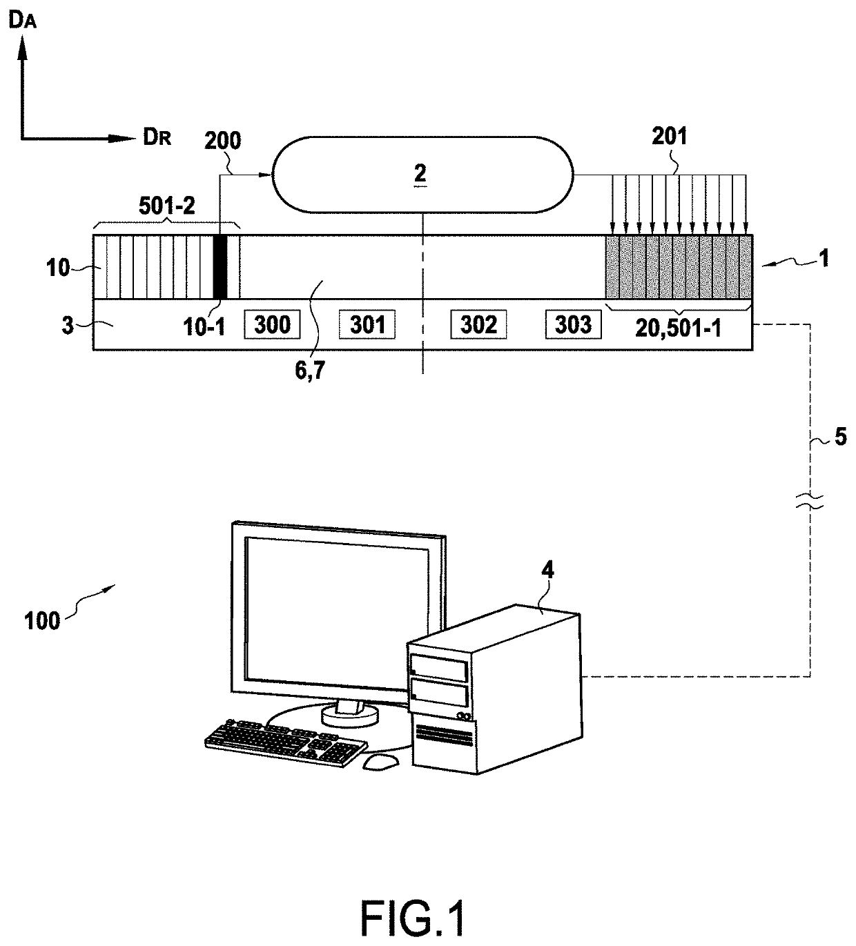
[0038]FIG. 1 shows a device 100 for non-destructive characterization by ultrasound waves in order to determine the characteristics of a material 2. The device 100 comprises an ultrasound transducer 1, i.e. a probe, having a plurality of emitter / receiver cells 10. Each emitter / receiver cell 10 may be switchable into an emit mode for emitting ultrasound waves towards the material 2 for characterizing, or into a receive mode for receiving ultrasound waves that have been transmitted and / or guided through said material 2. The transducer 1 is associated with control means 3 suitable for selecting and switching any cell 10 of the ultrasound transducer 1 into an emit mode, into a receive mode, or indeed to leave the cell 10 inactive. In the example shown, and as described in greater detail below, the control means 3 have switched one cell 10-1 (the cell marked in black) into emit mode and a set 20 of cells 10, specifically eleven cells, into receive mode (cells marked in gray), while the ot...


PUM

PropertyMeasurementUnit
DAaaaaaaaaaa
timeaaaaaaaaaa
anisotropicaaaaaaaaaa

Abstract

A characterization device for non-destructively characterizing a material includes emitter/receiver cells, each cell being able, in an emit mode, to emit ultrasound waves towards the material for characterizing, and, in a receive mode, to receive ultrasound waves that have been transmitted through the material. The non-destructive characterization device includes a ring made up of a plurality of adjacent angular sectors, each angular sector including ultrasound cells stacked in a radial direction of the ring.

Description

BACKGROUND OF THE INVENTION[0001]The invention relates to a device for non-destructively characterizing a material and to a non-destructive characterization method performed by the device.[0002]Non-destructive testing (NDT) and characterization methods are of great importance, in particular in the automobile, health, or indeed aviation fields. These methods can be used to characterize the integrity state of parts (e.g. airplane wings, engine parts), of structures (e.g. polycrystalline structures, multilayer structures), and more generally of materials at any time in their life cycle, e.g. during production, use, or maintenance. The use of these methods is even more important in the field of aviation since the structures in question, whether single pieces or assemblies, need to present characteristics that satisfy extremely severe standards.[0003]Various known methods consist in applying ultrasound excitation as emission from a transducer into a material that is to be characterized, ...

Claims


Application Information

Patent Timeline
Patent Type & Authority Applications(United States)
IPC IPC(8): G01N29/22B06B1/02B06B1/06
CPCG01N2291/0289G01N29/4445G01N29/221B06B1/0284G01N2291/023G01N29/2437G01N2291/048B06B1/0625G01N2291/106G01N29/041G01S15/8922G01N2291/02827G01N2291/263G01S15/8913G01S15/8927G01N29/07G01N2291/011G01N29/04
Inventor DUCOUSSO, MATHIEU LOICJENSON, FREDERIC
Owner SAFRAN
Why Eureka
Try Eureka