Crimp Interconnect Device, Crimped Arrangement and Method for Making a Crimped Arrangement

a technology of crimp interconnect and crimping, which is applied in the direction of connection contact material, connection effected by permanent deformation, line/current collector details, etc., can solve the problems of high risk of overheating of the joint, mechanical stability of the joint may be deteriorated, and conventional press rings, etc., to prevent mechanical deformation of the crimping pmt, easy deformation, and good stability

Active Publication Date: 2020-03-19
EPCOS AG
View PDF8 Cites 0 Cited by
  • Summary
  • Abstract
  • Description
  • Claims
  • Application Information

AI Technical Summary

Benefits of technology

[0011]The second material may be tin, which may be easily deformed at room temperature. The barrel body may be a sleeve having an optional chamfer, which provides good stability. The barrel body may be made of copper.
[0012]The above-mentioned crimp interconnect device may be used in a crimped arrangement comprising the crimp interconnect device being crimped to a plurality of conductors. The conductors may be single-strand wires, also called solid wires, or multi-strand wires, also referred to as litz wires, or a combination thereof. The second material is less hard than the softer crimped conductors. Therefore the second material additionally added to a crimp interconnect device's barrel body prevents mechanical deformation of the crimped pmts. It is not necessary to use expensive connection parts between the aluminum and copper wires. Crimping is made possible by means of one press ring forming the crimp interconnect device.

Problems solved by technology

Due to cross-section reduction the electrical conductivity and the mechanical stability of the joint may be deteriorated, which may cause a high risk of overheating the joint due to electric overload and of mechanical breaking due to vibrations.
If crimping together a solid aluminum wire and a solid copper wire, the above-mentioned problems would arise.
Conventional press rings involve the above-mentioned problem and are not suitable for crimping together aluminum and copper in a proper way.

Method used


Image

  • Crimp Interconnect Device, Crimped Arrangement and Method for Making a Crimped Arrangement
  • Crimp Interconnect Device, Crimped Arrangement and Method for Making a Crimped Arrangement

Examples


Embodiment Construction

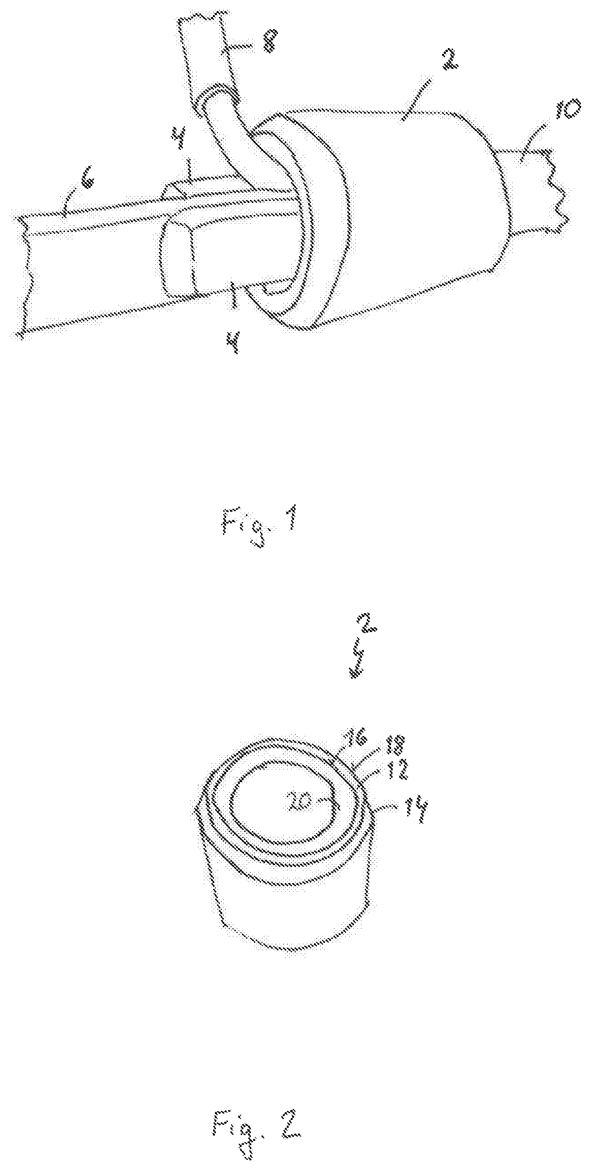
[0022]FIG. 1 shows a three-dimensional view of an embodiment of a crimped arrangement connecting several conductors. The arrangement comprises a crimp interconnect device including a barrel, which is embodied as a press ring 2 connecting two aluminum wires 4, a copper wire 6 and a soft copper wire 8 having a stripped end to a further wire 10. The aluminum wires 4, the copper wire 6 and the soft copper wire 8 have been inserted into one end of the press ring 2; the further wire 10 has been inserted into the other end of the press ring 2. The press ring 2 is deformed by an indent crimp 22 (not visible in FIG. 1), which forms a connection of the wires 4, 6, 8, 10 and the press ring 2. A single indent crimp 22 may be formed by an indentor ram, which causes a crescent cross-section deformation. The barrel 12 may be deformed by a suitable means, e.g., a hand tool or an automatic wire processing system.

[0023]FIG. 2 shows an embodiment of a crimp interconnect device being a press ring 2. It...


PUM

PropertyMeasurementUnit
widthaaaaaaaaaa
widthaaaaaaaaaa
ductileaaaaaaaaaa

Abstract

A crimp interconnect device, a crimped arrangement and a method for making a crimped arrangement are disclosed. In an embodiment a crimp interconnect device includes a deformable barrel body having an inner side and an outer side and a first material, and a second material that is softer than the first material, wherein the second material is arranged on the inner side.

Description

[0001]This patent application is a national phase filing under section 371 of PCT / EP2018 / 076474, filed Sep. 28, 2018, which claims the priority of German patent application 102017123286.9, filed Oct. 6, 2017, each of which is incorporated herein by reference in its entirety.TECHNICAL FIELD[0002]The invention relates to a crimp interconnect device, a crimped arrangement including such a crimp interconnect device and a method for making a crimped arrangement.BACKGROUND[0003]Crimping allows connecting two pieces of ductile material by deforming at least one of them. A ductile material is a solid material having the ability to deform under mechanical or tensile stress. Crimping may be used to form a connection between a crimp interconnect device, also referred to as a crimp electrical interconnect device, and one or more conductors, which may be wires. The wires are inserted into a barrel of the interconnect device. Then the barrel is deformed in such a manner that it holds the wires. T...

Claims


Application Information

Patent Timeline
Patent Type & Authority Applications(United States)
IPC IPC(8): H01R4/20H01R43/048H01R4/62
CPCH01R43/048H01R4/62H01R4/20H01R43/04
Inventor ZSELI, SZABOLCS
Owner EPCOS AG
Why Eureka
Try Eureka