Optical frequency stabilizer using optical fiber delay line, and method for generating stable optical frequency signal

a delay line and optical fiber technology, applied in the field of low-noise optical signal/microwave signal generation technology, can solve the problems of increasing the cost burden, complex structure of ofd-based stabilizers, and high cost, and achieve excellent noise performance, mechanical stability, and high cost.

Active Publication Date: 2020-03-19
KOREA ADVANCED INST OF SCI & TECH
View PDF0 Cites 10 Cited by
  • Summary
  • Abstract
  • Description
  • Claims
  • Application Information

AI Technical Summary

Benefits of technology

[0027]According to some embodiments, the frequency stabilizer has excellent noise performance, competitive price, and mechanical stability compared to the conventional optical frequency stabilizers or microwave frequency synthesizers.

Problems solved by technology

However, OFD-based stabilizers need high-performance vacuum chamber, vibration isolation system and temperature stabilization system.
OFD-based stabilizers are complex in structure, large in size, and expensive.
In addition, the stabilizer known so far can stabilize only one laser, which greatly increases the cost burden when multiple lasers are supposed to be stabilized.

Method used


Image

  • Optical frequency stabilizer using optical fiber delay line, and method for generating stable optical frequency signal
  • Optical frequency stabilizer using optical fiber delay line, and method for generating stable optical frequency signal
  • Optical frequency stabilizer using optical fiber delay line, and method for generating stable optical frequency signal

Examples


Embodiment Construction

[0036]In the following detailed description, only certain exemplary embodiments of the present disclosure have been shown and described, simply by way of illustration. As those skilled in the art would realize, the described embodiments may be modified in various different ways, all without departing from the spirit or scope of the present disclosure. Accordingly, the drawings and description are to be regarded as illustrative in nature and not restrictive. Like reference numerals designate like elements throughout the specification.

[0037]Throughout the specification, unless explicitly described to the contrary, the word “comprise” and variations such as “comprises” or “comprising”, will be understood to imply the inclusion of stated elements but not the exclusion of any other elements.

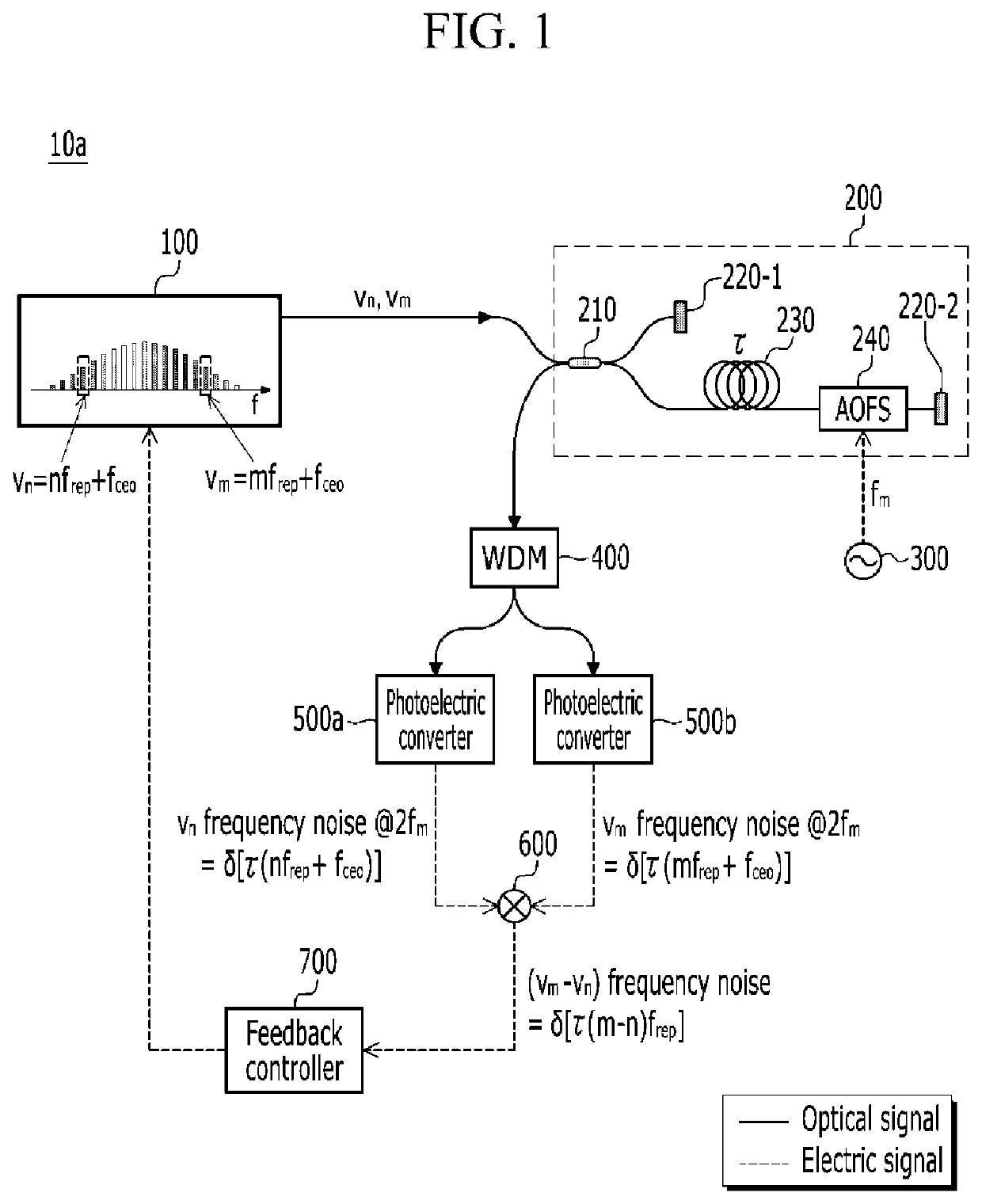
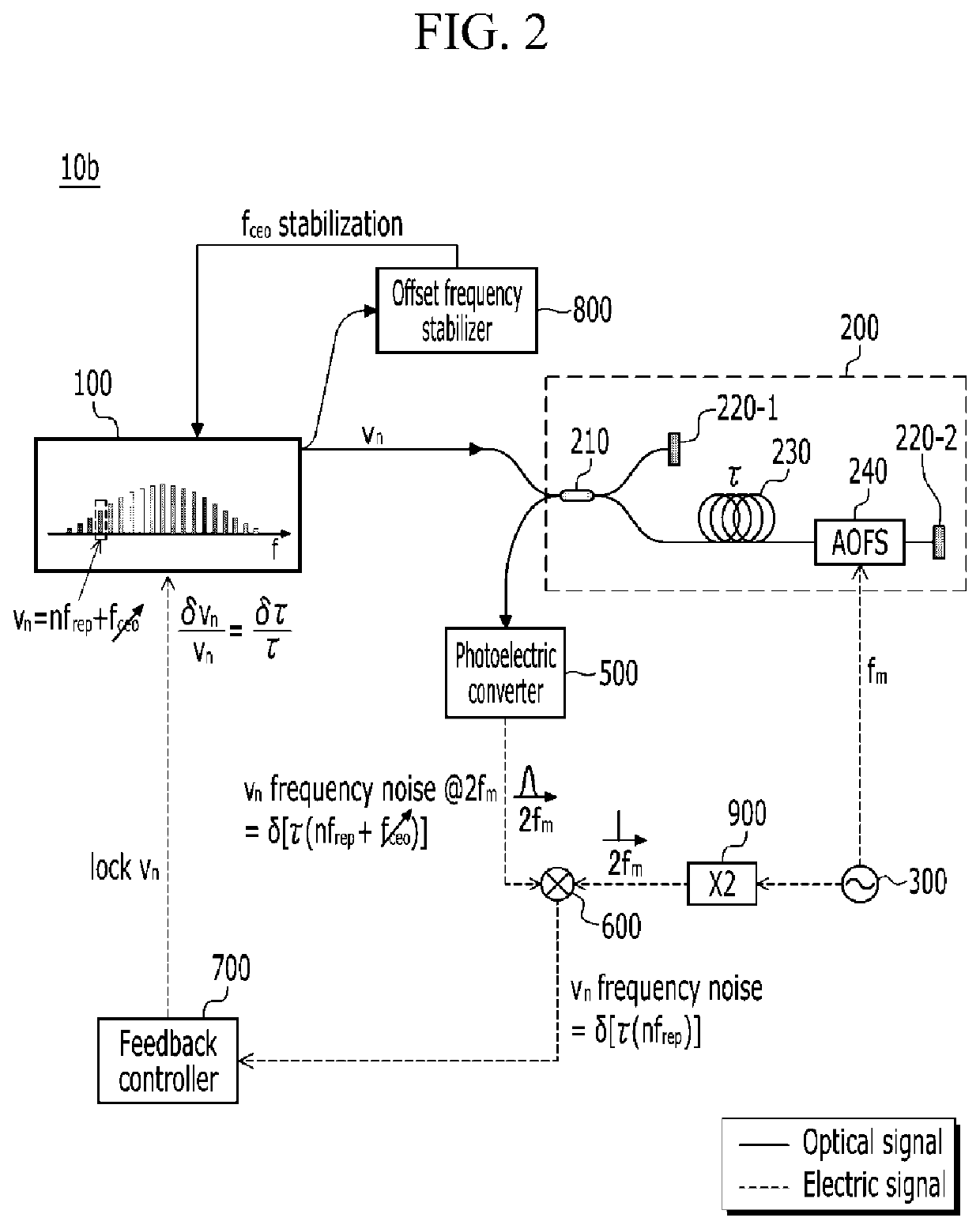
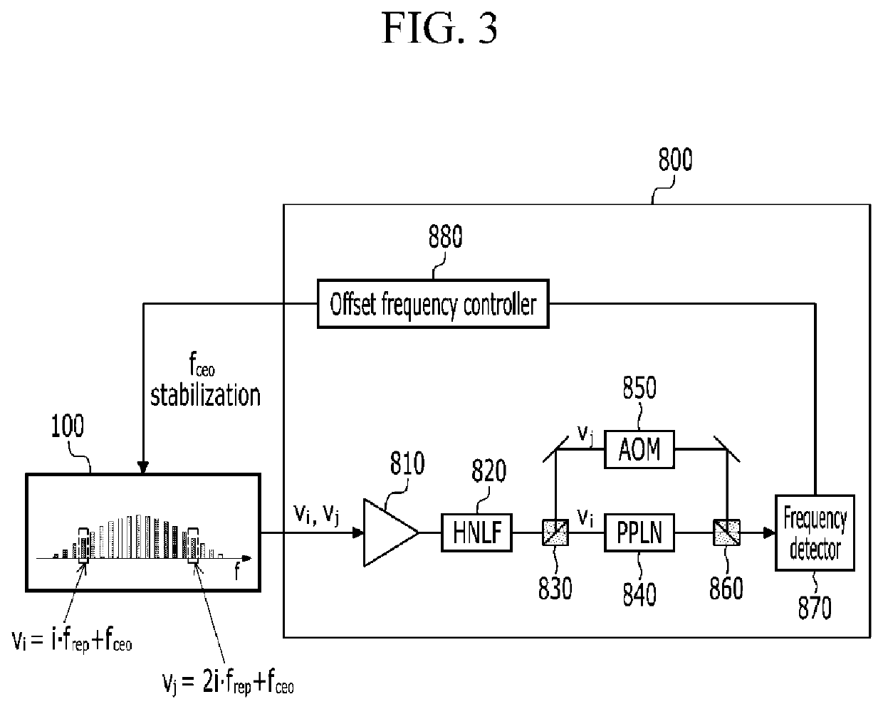
[0038]A pulsed laser is represented as a discontinuous spectrum of constant frequency intervals (frep) in the frequency domain, which may be referred to as an optical frequency comb. Therefore, the fr...


PUM


Abstract

A frequency stabilizer includes: a delay line interferometer that receives an optical signal corresponding to one frequency mode of a pulsed laser, divides and transmits the received optical signal to a reference arm and a delay arm including an optical fiber delay line, and then outputs an interference signal between signals passing through the reference arm and the delay arm; a photoelectric converter that converts the interference signal into an electrical signal; a mixer that generates a baseband signal of the electrical signal by mixing a carrier frequency signal; and a feedback controller that transmits a control signal generated based on the baseband signal to the pulsed laser. The optical signal passing through the delay arm is weighted with a delay time caused by the optical fiber delay line compared to the optical signal passing through the reference arm, and the optical signal passing through the delay arm is frequency shifted to a carrier frequency of an oscillator. A carrier-envelope offset frequency of the pulsed laser is stabilized by an offset frequency stabilizer.

Description

CROSS-REFERENCE TO RELATED APPLICATION[0001]This application claims priority to and the benefit of Korean Patent Application No. 10-2018-011348 and 10-2019-0099102 filed in the Korean Intellectual Property Office on Sep. 18, 2018 and Aug. 13, 2019, the entire contents of which are incorporated herein by reference.BACKGROUND(a) Field[0002]The present disclosure relates to low-noise optical signal / microwave signal generation technology.(b) Description of the Related Art[0003]Low-noise optical signal / microwave signal generation technology is the basic technology of various measurement systems, including defense systems. Therefore, noise performance superior to the prior art have been continuously researched. At the same time, there is a high demand for optical frequency stabilizers or microwave synthesizers that are cost-competitive and mechanically robust for commercialization.[0004]High-performance stabilizers known so far use Optical Frequency Division (OFD) technology that interfer...

Claims


Application Information

Patent Timeline
Patent Type & Authority Applications(United States)
IPC IPC(8): H01S3/137H04J14/02H01S3/139H01S3/067H01S3/10
CPCH01S3/1398H01S2301/02H01S3/137H04J14/0202H01S3/067H01S3/10007H01S3/1304H01S3/1305H01S3/1307H01S3/0085H01S3/005
Inventor KIM, JUNGWONKWON, DOHYEON
Owner KOREA ADVANCED INST OF SCI & TECH
Why Eureka
Try Eureka