Method for controlling a wave-energy-converter system taking into account uncertainties

a technology of wave energy conversion and uncertainty, applied in the direction of proportional integration algorithms, machines/engines, mechanical apparatus, etc., can solve the problems of insufficient optimal control of wave energy conversion system, inability to adapt to the gains, and insufficient power generation, so as to achieve the effect of maximizing the power generated by power take-o

Active Publication Date: 2020-03-26
INST FR DU PETROLE
View PDF0 Cites 4 Cited by
  • Summary
  • Abstract
  • Description
  • Claims
  • Application Information

AI Technical Summary

Benefits of technology

[0032]According to one aspect, the power generated by the power take-off is maximized by accounting for the efficiency of the power take-off.

Problems solved by technology

These methods therefore do not allow the gains to be adapted “wave to wave”, i.e. at a frequency that would allow real-time control (for example a frequency comprised between 10 and 100 Hz, i.e. a sampling period comprised between 10 and 100 ms).
Thus, the high reaction time of these methods does not allow the wave-energy-converter system to be controlled optimally and the power generated is therefore not optimal.
In addition, in the above prior art there are no examples of control methods that allow P or PI control-law gains that are optimal from the point of view of maximization of the harvested energy to be calculated in the presence of uncertainties in the dynamics of the wave-energy-converter system, irrespectively of whether these uncertainties are present in the dynamics of the primary converter (movable portion, such as a float) or of the secondary converter (PTO).
If the fidelity (to reality) of this dynamic model is not sufficient, the performance of the control method will be affected.
Specifically, the methods described in these patent applications are not robust with respect to uncertainties in the wave-energy-converter system, irrespectively of whether these uncertainties relate to the movable portion or to the power take-off.

Method used


Image

  • Method for controlling a wave-energy-converter system taking into account uncertainties
  • Method for controlling a wave-energy-converter system taking into account uncertainties
  • Method for controlling a wave-energy-converter system taking into account uncertainties

Examples


example of application

[0232]The features and advantages of the method according to the invention will become more clearly apparent on reading about the following example of application.

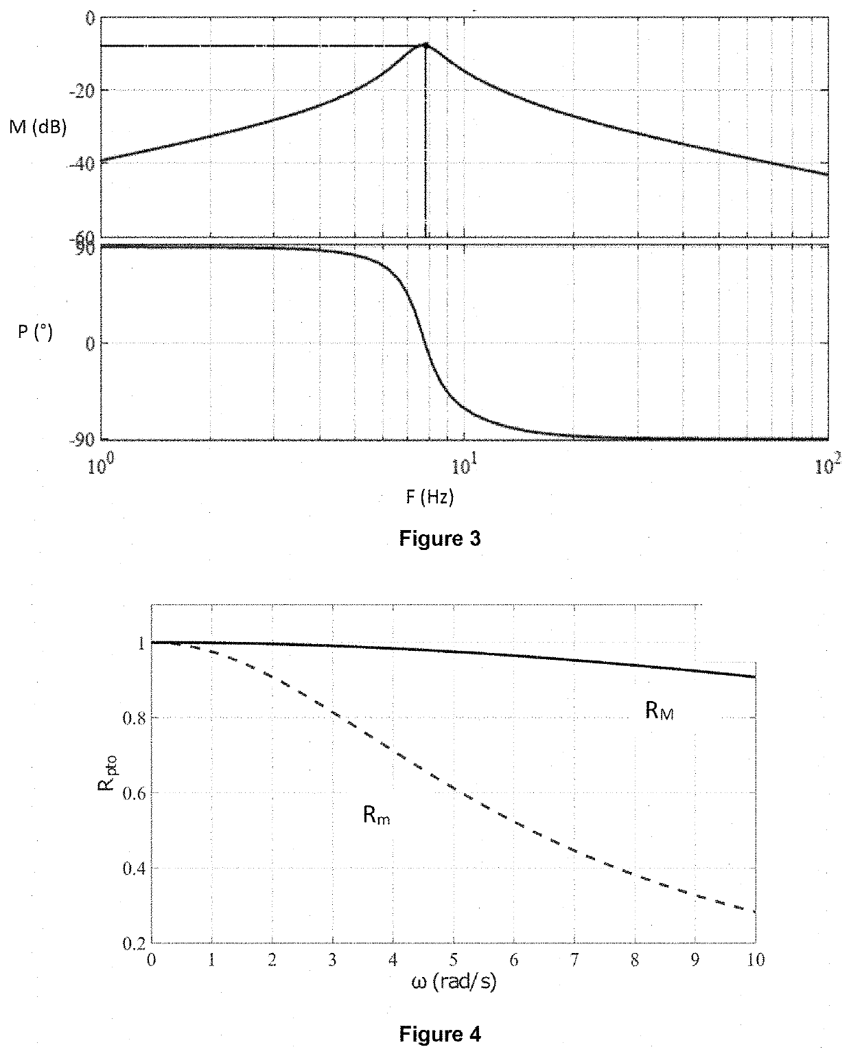
[0233]In this example, a float such as described in FIG. 2 is considered, the force-speed dynamics (speed response to the sum of the forces applied to the float) of which are given by the following transfer function:

Zi(s)=s6+208.6s5+8.583·104s4+8.899·106s3+1.074·108s2+7.031·108s1.44s7+300.4s6+1.237·105s5+1.284·107s4+1.652·108s3+2.106·109s⋀2+9.988·109s+6.539·1010

[0234]This function gives the Bode plot of FIG. 3. The top part of FIG. 3 is a curve of amplitude M in dB as a function of frequency F in Hz. The bottom part of FIG. 3 is a curve of phase shift P in ° (degrees) as a function of frequency F in Hz. It is a question of a typical Bode plot for a wave-energy-converter system of the type with a point-like absorber. The transfer function describes the dynamics of a small-scale (1:20) prototype to which the method has been ...


PUM


Abstract

The present invention is a method for controlling a wave-energy-converter system, wherein the gains of a control law having a proportional component are optimally determined in terms of the harvest of energy, and are robust with respect to uncertainties in the dynamics of the wave-energy-converter system. The harvest of energy is maximized for the worst case described by the uncertainties, by solving a semidefinite-positive optimization problem.

Description

CROSS REFERENCE TO RELATED APPLICATIONS[0001]Reference is made French Application No. 18 / 58.714 filed Sep. 25, 2018, which is incorporated herein by reference in its entirety.BACKGROUND OF THE INVENTIONField of the Invention[0002]The invention relates to devices for converting the energy of waves into electrical or hydraulic energy.Description to the Prior Art[0003]Sources of renewable energy have seen a substantial amount of interest. The fact that they are clean, free and inexhaustible is a major advantage in a world beset by the inexorable decrease in available fossil fuels and increasingly conscious of the need to preserve the planet. Among these sources, wave energy, which is a relatively overlooked source relative to those that have received more media attention (such as wind or solar power) has a contribution to play in the indispensable diversification of the exploitation of renewable energy. The devices commonly referred to as “wave-energy converters” are particularly of in...

Claims


Application Information

Patent Timeline
Patent Type & Authority Applications(United States)
IPC IPC(8): F03B15/00F03B13/18G06F17/16
CPCF05B2270/705F03B13/1845G06F17/16F03B15/00F03B13/16F05B2270/20Y02E10/30
Inventor TONA, PAOLINONGUYEN, HOAI-NAM
Owner INST FR DU PETROLE
Why Eureka
Try Eureka