Transparent layered element comprising a display region

a technology of layered elements and display regions, which is applied in the direction of instruments, furniture parts, other domestic objects, etc., can solve the problems of limiting the clarity of view, not allowing images to be formed, and not conceivable to use transparent standard glazing as projection screens, etc., to promote diffuse reflection, uniform overall visual appearance, and good luminosity of images projected on the screen zone

Active Publication Date: 2020-03-26
SAINT-GOBAIN GLASS FRANCE
View PDF0 Cites 2 Cited by
  • Summary
  • Abstract
  • Description
  • Claims
  • Application Information

AI Technical Summary

Benefits of technology

[0050]a uniform overall visual appearance of the layered element, from one or other of its outer layers, owing to the transition zone, allowing integration of the screen zone relative to the peripheral zone without pronounced visual delimitation between the two zones.
[0051]Transparent glazing comprising a transparent layered element of this kind thus has a uniform overall visual appearance and at the same time makes it possible to project images in at least one zone of the glazing dedicated to projection, which corresponds to the or each screen zone of the layered element, and ensure clear vision through the glazing...

Problems solved by technology

It is not conceivable to use transparent standard glazing as projection screens.
In fact, this glazing does not have the property of diffuse reflection, and therefore does not allow images to be formed on any one of its faces and throws back reflections just like a mirror.
However, it has been found that with such glazing, in certain conditions of use, in particular when the lumin...

Method used


Image

  • Transparent layered element comprising a display region
  • Transparent layered element comprising a display region
  • Transparent layered element comprising a display region

Examples


first embodiment

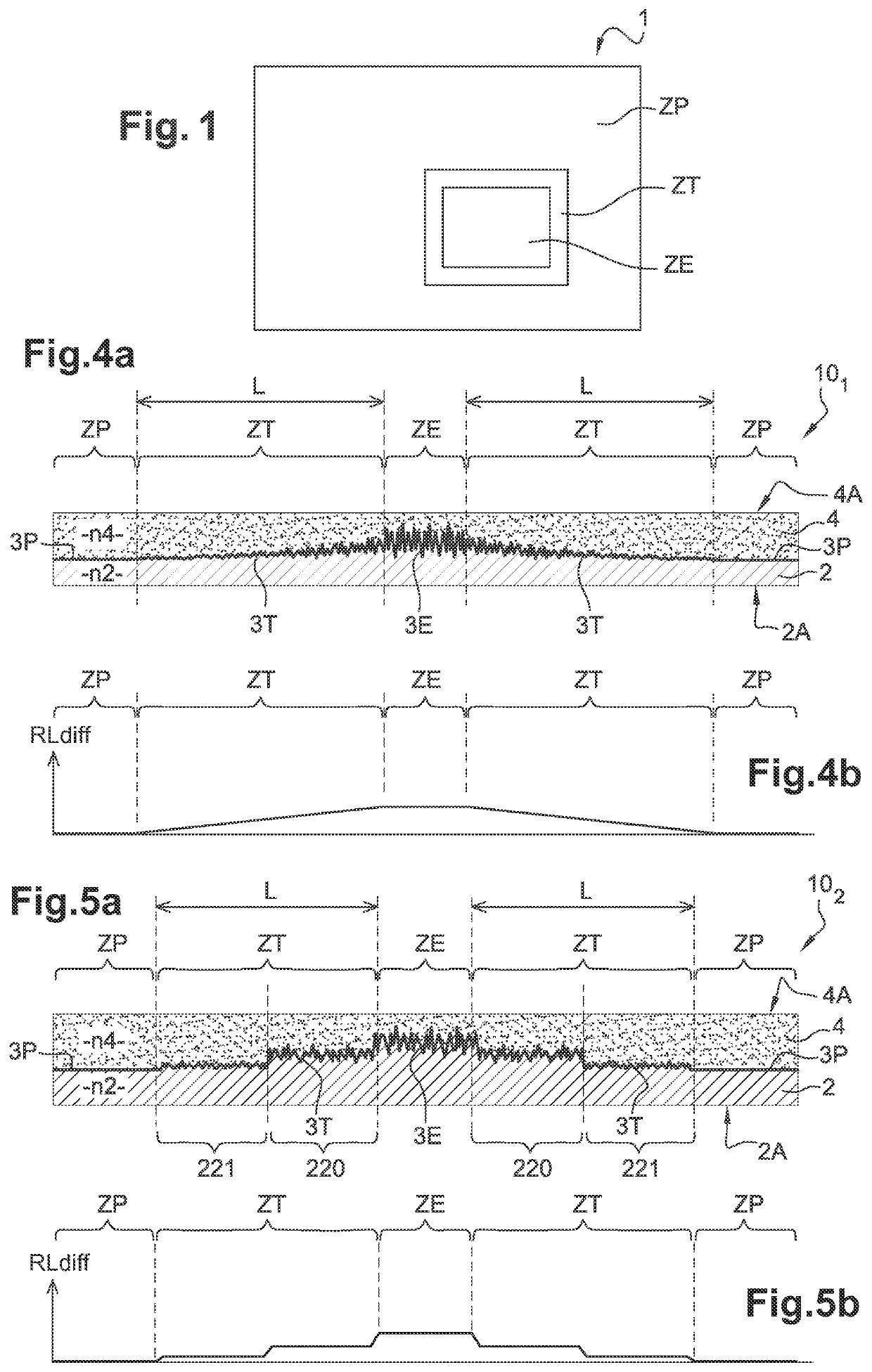
[0138]In a layered element 101 shown in FIGS. 4a and 4b, the decrease in the variation of the diffuse light reflection in the transition zone ZT going from the screen zone ZE to the peripheral zone ZP is obtained by continuous variation of the roughness profile of the middle layer 3T of the transition zone ZT, in the sense of a decrease of the mean square slope Rdq(ZT) from the screen zone ZE to the peripheral zone ZP, whereas the middle layers 3E, 3T, 3P all have an identical thickness and an identical chemical composition.

[0139]As an example, referring to FIG. 4a: [0140]in the screen zone ZE, the middle layer 3E is textured, with a mean square slope Rdq(ZE) of the order of 5°;[0141]in the peripheral zone ZP, the middle layer 3P is smooth, with a mean square slope Rdq(ZP) of less than 0.2°;[0142]in the transition zone ZT, which has a width L of 2.5 mm, the middle layer 3T is textured with a mean square slope Rdq(ZT) that decreases continuously, from the value of the mean square slo...

second embodiment

[0143]In a layered element 102 shown in FIGS. 5a and 5b, the decrease in the variation of the diffuse light reflection in the transition zone ZT going from the screen zone ZE to the peripheral zone ZP is obtained by stepped variation of the roughness profile of the middle layer 3T of the transition zone ZT, in the sense of a decrease of the mean square slope Rdq(ZT) from the screen zone ZE to the peripheral zone ZP, whereas the middle layers 3E, 3T, 3P all have an identical thickness and an identical chemical composition.

[0144]As an example, referring to FIG. 5a: [0145]in the screen zone ZE, the middle layer 3E is textured, with a mean square slope Rdq(ZE) of the order of 5°;[0146]in the peripheral zone ZP, the middle layer 3P is smooth, with a mean square slope Rdq(ZP) of less than 0.2°;[0147]in the transition zone ZT, which has a width L of 5 mm, the middle layer 3T is textured with a mean square slope Rdq(ZT) that decreases in two successive steps 220, 221 such that: for step 220...

third embodiment

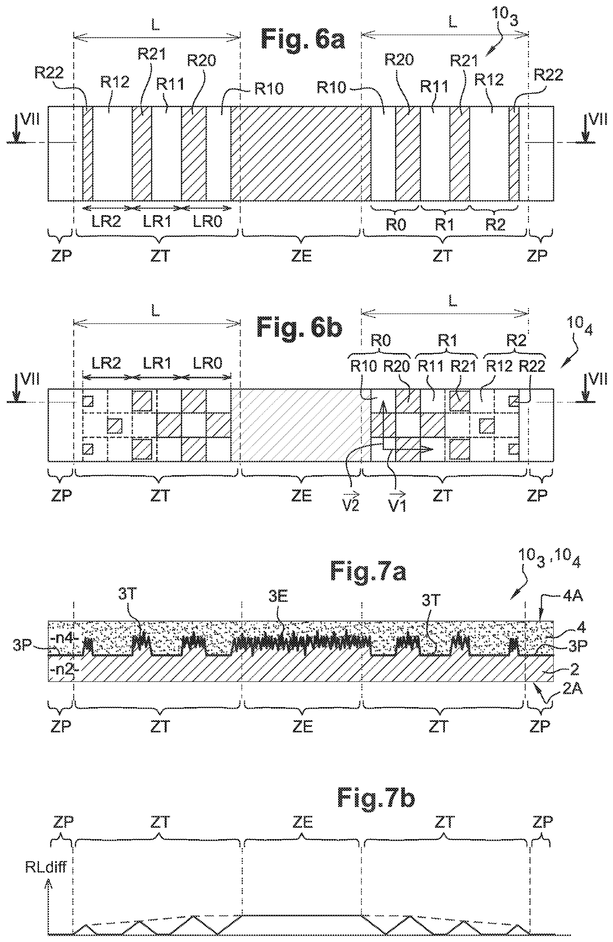
[0149]For the layered element 103 shown in FIG. 6a, which corresponds to a reduction of the density of portions with diffuse reflection by alternation of smooth bands and textured bands:[0150]in the screen zone ZE, the middle layer 3E is textured, with a mean square slope Rdq(ZE) of the order of 5°;[0151]in the peripheral zone ZP, the middle layer 3P is smooth, with a mean square slope Rdq(ZP) of less than 0.2°;[0152]in the transition zone ZT, which has a width L of 6 mm, the roughness profile of the middle layer 3T is discontinuous in the direction joining the screen zone ZE to the peripheral zone ZP.

[0153]More precisely, the transition zone ZT comprises three successive regions R0, R1, R2 going from the screen zone ZE to the peripheral zone ZP, where each region is formed by combining two bands comprising in each case a smooth band R10, R11, R12 closer to the screen zone ZE, where the middle layer 3T has the same roughness profile as the peripheral zone ZP, i.e. a mean square slo...


PUM

PropertyMeasurementUnit
Fractionaaaaaaaaaa
Angleaaaaaaaaaa
Thicknessaaaaaaaaaa

Abstract

A layered element includes two transparent outer layers having approximately the same refractive index and each having a smooth outer main surface, the layered element including a screen zone with properties of diffuse reflection and specular transmission comprising a textured middle layer interposed between the outer layers, a peripheral zone with properties of specular reflection and specular transmission, and a transition zone with properties of diffuse reflection and specular transmission between the screen zone and the peripheral zone, which includes a textured middle layer interposed between the outer layers. The diffuse light reflection at any point of the transition zone is less than or equal to the diffuse light reflection at any point of the screen zone and the variation of the diffuse light reflection in the transition zone from the screen zone to the peripheral zone, in any direction joining the screen zone to the peripheral zone, is decreasing.

Description

TECHNICAL FIELD OF THE INVENTION[0001]The technical field of the invention is that of transparent glazing comprising a transparent layered element with properties of diffuse reflection defining at least one screen zone that can serve as a projection screen or back projection screen. Transparent glazing of this kind that can serve as a projection screen or back projection screen finds application, in particular, in the field of transport, for example for making glazing for aircraft, trains, motor vehicles (cars, trucks, etc.), in particular windscreens, side glazing or roof glazing.TECHNOLOGICAL BACKGROUND OF THE INVENTION[0002]Known glazing comprises the standard transparent glazing, which gives rise to specular transmission and reflection of radiation incident on the glazing, and translucent glazing, which give rise to diffuse transmission and reflection of radiation incident on the glazing.[0003]Usually, reflection by glazing is called diffuse when radiation incident on the glazin...

Claims


Application Information

Patent Timeline
IPC IPC(8): G03B21/62G02B5/02B32B17/10
CPCB32B17/10036G02B5/0221B32B17/1022G03B21/62B32B17/10174B32B17/10761B32B27/08B32B2307/304B32B2307/546B32B3/30B32B2605/18B32B3/28B32B27/42B32B2250/05B32B27/40B32B2250/03B32B2307/422B32B2605/10B32B27/06B32B2255/10B32B2307/738B32B2255/26B32B2307/418B32B2307/538B32B2255/28B32B2307/732B32B1/00B32B2479/00B32B27/281B32B27/34B32B2307/412B32B2255/20B32B27/322B32B2307/40B32B27/36B32B27/365B32B7/12B32B2307/204B32B2451/00B32B2457/20B32B2250/24B32B2307/30B32B27/308B32B27/306B32B2419/00B32B2605/08B32B2255/205B32B27/304B32B2605/006B32B17/1011B32B17/10146B32B17/10201B32B17/10577B32B17/10005B32B2333/12B32B7/023B32B17/06B32B17/10119B32B17/10018B32B17/10559G02B27/01
Inventor SCHIAVONI, MICHELEOZANAM, CÉCILEGAYOUT, PATRICK
Owner SAINT-GOBAIN GLASS FRANCE
Why Eureka
Try Eureka