Tomosynthesis imaging apparatus and method for operating the same

a technology of tomosynthesis and imaging apparatus, which is applied in the field of tomosynthesis imaging apparatus and a method for operating the same, can solve the problems of limited arrangement interval of x-ray tubes, increase in imaging time, and increase in imaging time, and achieve the effect of reducing imaging tim

Active Publication Date: 2020-04-02
FUJIFILM CORP
View PDF0 Cites 0 Cited by
  • Summary
  • Abstract
  • Description
  • Claims
  • Application Information

AI Technical Summary

Benefits of technology

[0007]Therefore, the inventors have studied a technique which provides a plurality of X-ray tubes with different irradiation angles in order to reduce the imaging time. In this configuration, the movement range of the X-ray tube is narrower than that in a case in which one X-ray tube is moved and the number of times the X-ray tube is stopped is reduced by a value corresponding to an increase in the number of X-ray tubes. Therefore, it is possible to reduce the imaging time.
[0008]However, in a case in which a plurality of X-ray tubes are provided, the arrangement interval of the X-ray tubes is limited by the size of each X-ray tube. In a case in which the arrangement interval of a plurality of X-ray tubes increases, the number of captured projection images in the unit angle is reduced. In a case in which the number of captured images is reduced, the amount of information required to reconstruct the tomographic image is reduced and the number of artifacts in the reconstructed tomographic image increases.
[0009]An object of the technology according to the present disclosure is to provide a tomosynthesis imaging apparatus that can reduce an imaging time while suppressing an artifact in a tomographic image, as compared to the related art in which tomosynthesis imaging is performed while one X-ray tube is being moved, and a method for operating the tomosynthesis imaging apparatus.
[0031]According to the technology of the present disclosure, it is possible to reduce the imaging time while suppressing an artifact in a tomographic image, as compared to the related art in which tomosynthesis imaging is performed while one X-ray tube is being moved.

Problems solved by technology

Moreover, in the tomosynthesis imaging, in addition to the movement of one X-ray tube, the X-ray tube may be stopped whenever X-rays are emitted, which also causes an increase in the imaging time.
Since the long imaging time is painful for the object, there is a demand to reduce the imaging time in the tomosynthesis imaging as much as possible.
However, in a case in which a plurality of X-ray tubes are provided, the arrangement interval of the X-ray tubes is limited by the size of each X-ray tube.

Method used


Image

  • Tomosynthesis imaging apparatus and method for operating the same
  • Tomosynthesis imaging apparatus and method for operating the same
  • Tomosynthesis imaging apparatus and method for operating the same

Examples


first embodiment

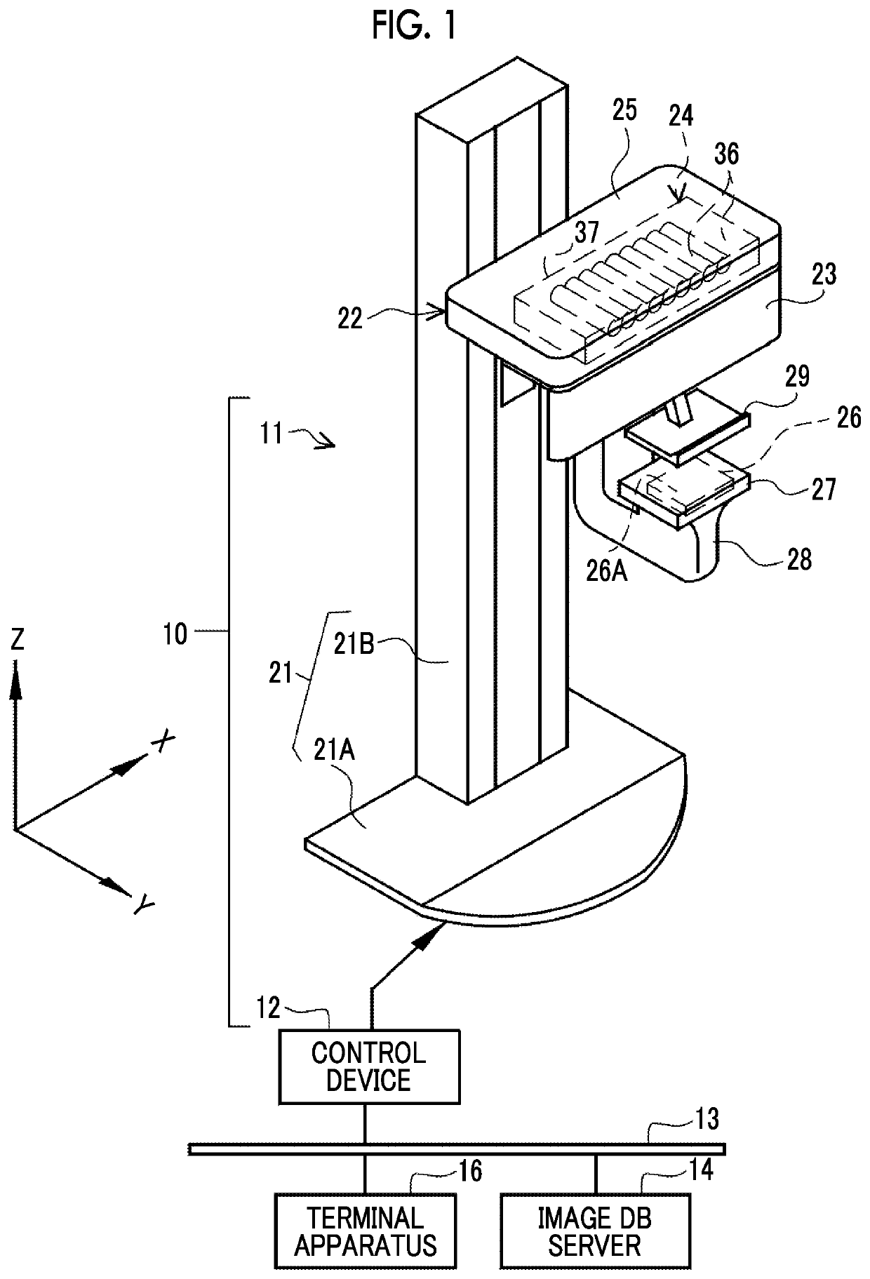
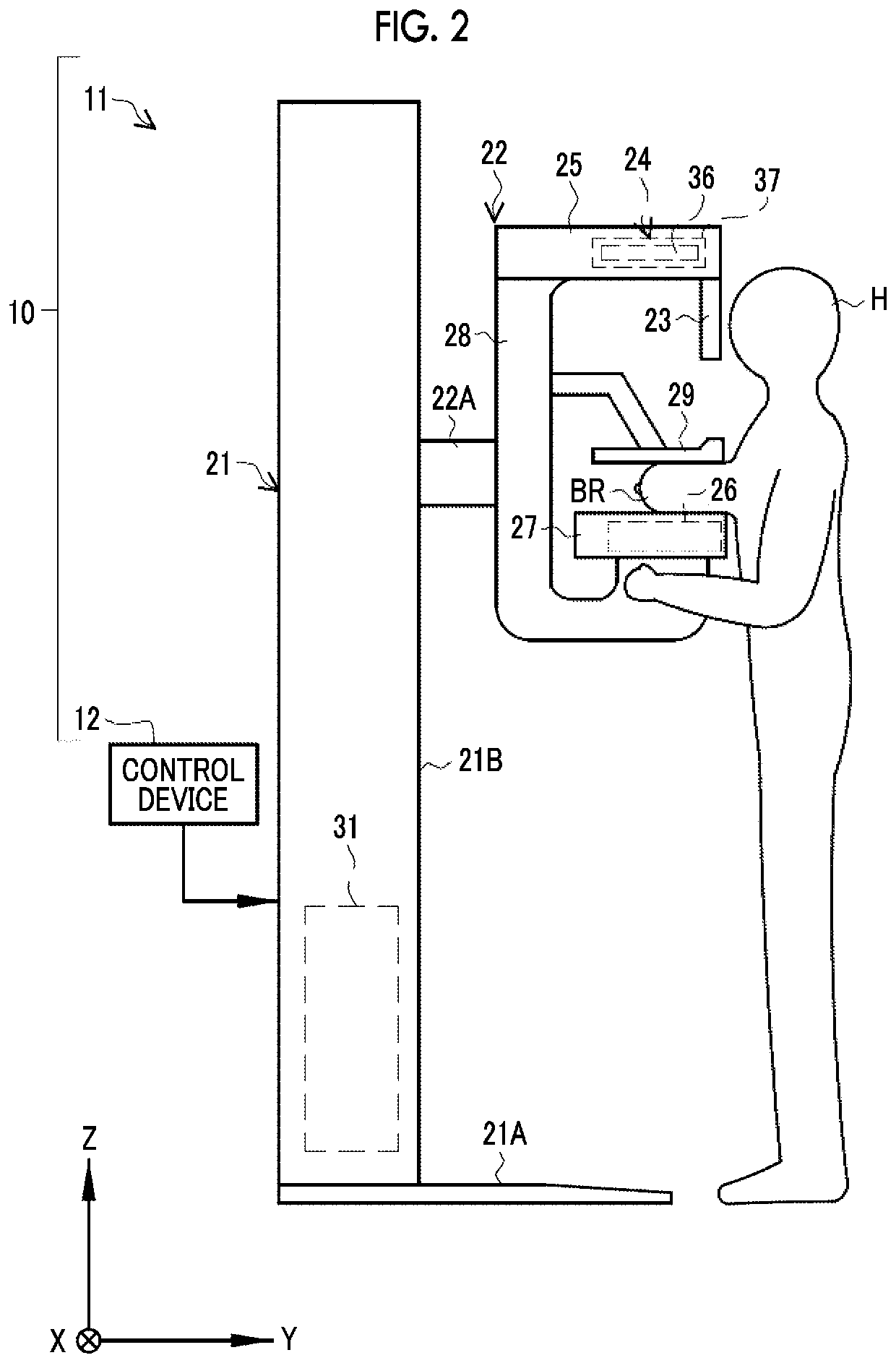
[0060]A mammography apparatus 10 illustrated in FIGS. 1 and 2 irradiates a breast BR of a subject H which is an object with X-rays and captures an X-ray image of the breast BR. The mammography apparatus 10 has a tomosynthesis imaging function and is an example of a tomosynthesis imaging apparatus. The mammography apparatus 10 includes an apparatus main body 11 and a control device 12.

[0061]The control device 12 is connected to an image database (DB) server 14 and a terminal apparatus 16 through a network 13 so as to communicate therewith. The X-ray image captured by the mammography apparatus 10 is transmitted from the control device 12 to the image DB server 14 and is accumulated in the image DB server 14. The image DB server 14 is, for example, a picture archiving and communication system (PACS) server. The terminal apparatus 16 reads an X-ray image from the image DB server 14 and displays the X-ray image. The terminal apparatus 16 is used by, for example, a doctor to browse the X-...

second embodiment

[0164]FIGS. 18 and 19 illustrate an X-ray source 242 according to a second embodiment. In the second embodiment, the description of the same points as those in the first embodiment will not be repeated and the difference from the first embodiment will be mainly described. In the X-ray source 242, a plurality of X-ray tubes 36 are arranged in an arc shape at equal intervals as viewed from the direction parallel to the imaging surface 26A. In the X-ray source 242 according to the second embodiment, similarly to the X-ray source 24 according to the first embodiment in which the X-ray tubes 36 are linearly arranged, the X-ray tubes 36 are arranged in a line in a plan view from the Z direction perpendicular to the imaging surface 26A. However, in the X-ray source 242, the plurality of X-ray tubes 36 are arranged in a convex arc shape in which the center in the arrangement direction in a plan view from the Z direction protrudes in a direction away from the imaging surface 26A. This is dif...

third embodiment

[0168]FIGS. 20 to 23 illustrate an X-ray source 243 according to a third embodiment. In the third embodiment, the description of the same points as those in the first embodiment will not be repeated and the difference from the first embodiment will be mainly described. As illustrated in FIG. 20, the X-ray source 243 includes two units, that is, a first unit 243A and a second unit 243B in which a plurality of X-ray tubes 36 are divided and accommodated. In this example, each of the first unit 243A and the second unit 243B includes six X-ray tubes 36 and a housing 37. The X-ray source 243 is accommodated in the radiation source accommodation portion 25 similarly to the X-ray source 24 according to the first embodiment.

[0169]As such, since the plurality of X-ray tubes 36 are divided and accommodated in a plurality of units, that is, the first unit 243A and the second unit 243B, for example, it is possible to replace only the unit accommodating a broken X-ray tube 36 and it is easy to p...


PUM


Abstract

A tomosynthesis imaging apparatus includes: a radiation detector having an imaging surface that detects radiation transmitted through an object and captures a projection image of the object; a radiation source that has a plurality of radiation tubes which emit the radiation to the imaging surface at different irradiation angles and selectively irradiates the object with the radiation from each of the plurality of radiation tubes; and a radiation source control unit that performs focal position control for switching between positions of focuses where the radiation is emitted for at least one of the plurality of radiation tubes to change the radiation irradiation angle of the radiation tube with respect to the imaging surface.

Description

CROSS-REFERENCE TO RELATED APPLICATIONS[0001]The present application claims priority under 35 U.S.C. § 119 to Japanese Patent Application No. 2018-182728, filed on Sep. 27, 2018. The above application is hereby expressly incorporated by reference, in its entirety, into the present application.BACKGROUND1. Technical Field[0002]The technology according to the present disclosure relates to a tomosynthesis imaging apparatus and a method for operating the same.2. Description of the Related Art[0003]In the medical field, an X-ray imaging apparatus using radiation, for example, X-rays has been known. A tomosynthesis imaging apparatus that can perform tomosynthesis imaging has been known as one of the X-ray imaging apparatuses. The tomosynthesis imaging apparatus comprises an X-ray detector, an X-ray source, and a movement mechanism for moving the X-ray source (for example, see JP2016-135319A). The X-ray detector has an image surface which is a two-dimensional plane as an imaging surface th...

Claims


Application Information

Patent Timeline
Patent Type & Authority Applications(United States)
IPC IPC(8): A61B6/00A61B6/02A61B6/04A61B6/10
CPCA61B6/482A61B6/4417A61B6/502A61B6/584A61B6/107A61B6/545A61B6/4441A61B6/025A61B6/0414A61B6/4007A61B6/4021A61B6/5258A61B6/54A61B6/5205A61B6/027
Inventor MAKINO, KAZUHIROMATSUURA, MASAYOSHI
Owner FUJIFILM CORP
Why Eureka
Try Eureka