Schmelzwanne und glasschmelzanlage

a glasschmelzanlage and glass melt technology, applied in the field of melt tanks, can solve the problems of insufficient bubble escape and high energy consumption of glass melt production, and achieve the effects of reducing the width of the basin, and reducing the flow speed of glass mel

Pending Publication Date: 2020-04-02
BETEILIGUNGEN SORG
View PDF2 Cites 2 Cited by
  • Summary
  • Abstract
  • Description
  • Claims
  • Application Information

AI Technical Summary

Benefits of technology

[0042]In the constriction region, the width of the basin is reduced following the melt tank. This has the advantage that the flow speed of the glass melt is reduced.
[0043]In an exemplary embodiment, in the constriction region at least one cooling element is situated on the cover of the constriction region. This at least one cooling element extends perpendicularly from the cover into the glass melt, has for example the shape of a plate, and is cooled e.g. by water. The at least one cooling element also acts to reduce the flow speed of the glass melt.

Problems solved by technology

This holds in particular for glass production, because the production of the glass melts is very energy-intensive.
It has turned out that supplying a glass melting plant, in particular a melt tank, exclusively with electrical energy, as is described for example in U.S. Pat. No. 3,885,945, leads to problems in the step of degassing the glass melt (refining) In the known electrical heating of a melt tank, the glass melt is heated using electrodes that are situated on the floor of the melt tank or in side walls and that extend into the melt.
They remain in the glass melt, and thus also remain in the product produced from the glass melt, where they cause quality problems.
In the designs shown there, having a refining bank after a step having a series of floor electrodes, or having a high floor wall after two rows of electrodes situated on the floor of the melt aggregate, bubbles cannot escape to an adequate degree.

Method used


Image

  • Schmelzwanne und glasschmelzanlage
  • Schmelzwanne und glasschmelzanlage
  • Schmelzwanne und glasschmelzanlage

Examples


Embodiment Construction

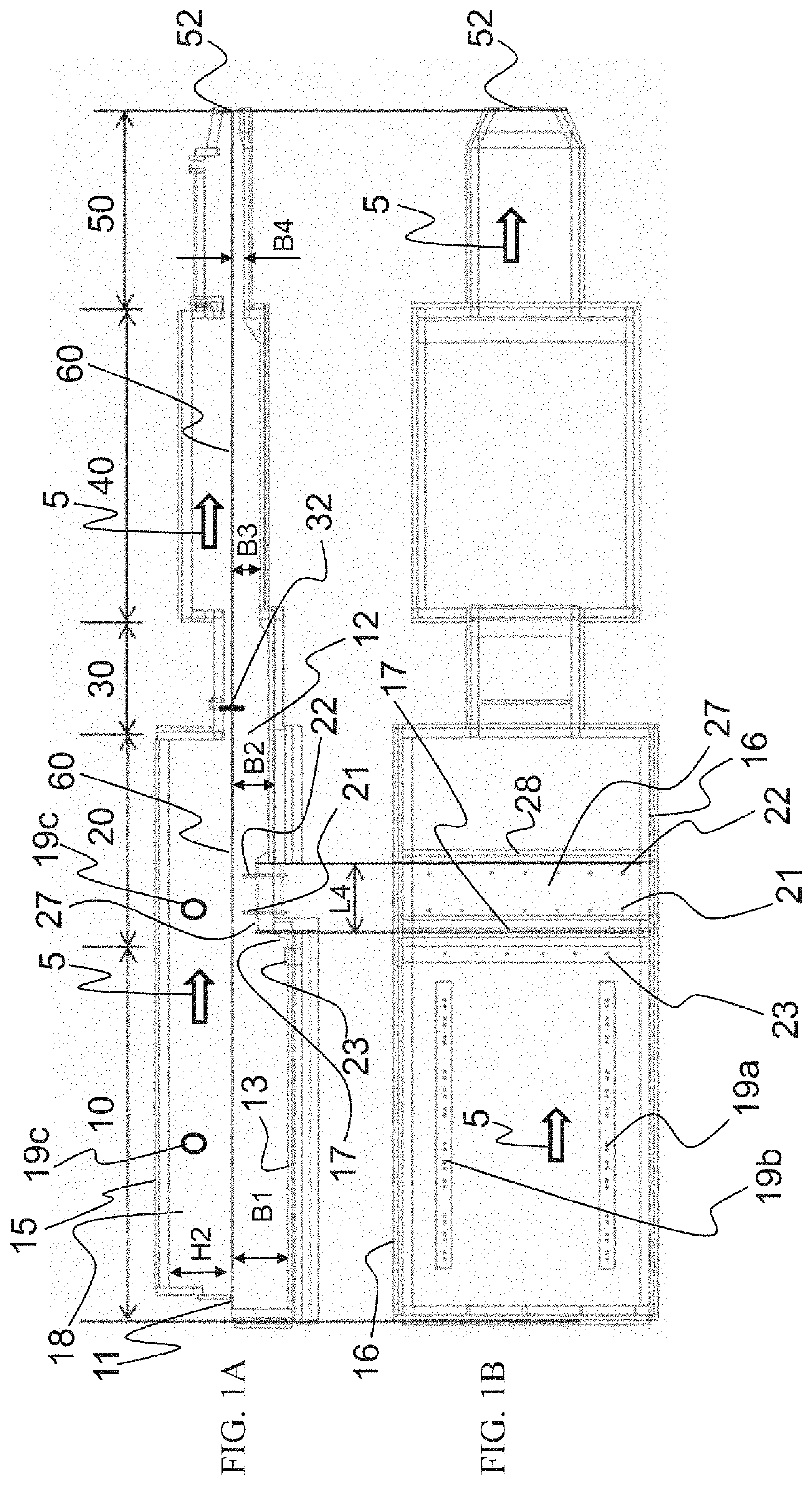
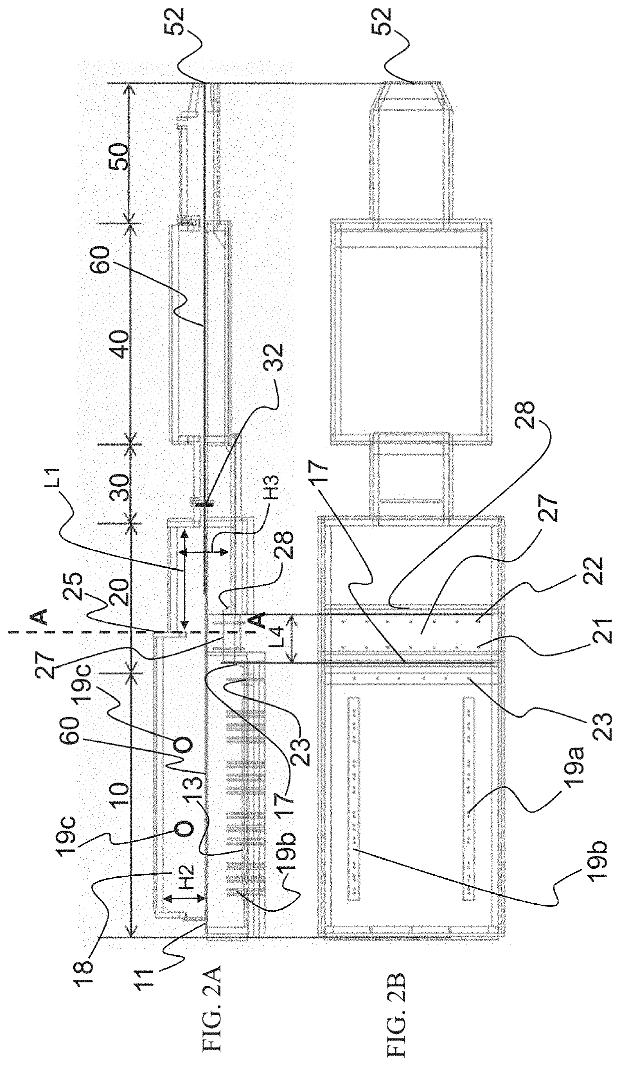
[0063]FIGS. 1A and 1B shows a first exemplary embodiment of a glass melting plant according to the present invention having a melt tank according to the present invention, suitable for example for a daily output of 400 t of molten glass.

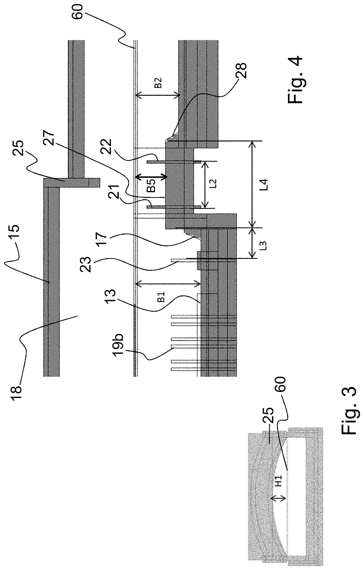
[0064]The melt tank includes the segments melting segment 10 and refining segment 20. The melt tank is followed by a constriction region 30, a conditioning region 40, and a channel 50. The starting materials for the production of the glass melt (primary raw materials and, possibly, shards) are continuously supplied at inlet opening 11 of the melt tank by a feed device (not shown). The starting materials are in particular melted in the melting segment 10 of the melt tank, and move (flow) together with glass melt 60 through refining segment 20, to outlet opening 12 of the melt tank, and further through constriction region 30, conditioning region 40, and channel 50, until they reach glass outlet opening 52. The direction of flow of glass melt 60 is indi...


PUM

PropertyMeasurementUnit
depthaaaaaaaaaa
depthaaaaaaaaaa
depthaaaaaaaaaa

Abstract

A melt tank for the production of a glass melt having a low portion of bubbles. The melt tank includes an inlet opening, an outlet opening, a floor, at least two side walls that adjoin the floor, a roof. The glass melt having a first bath depth in a melting segment, a second bath depth in a refining segment, and a third bath depth over a threshold between and smaller than the first and second bath depths. An electrical produced first heat energy is supplied via a multiplicity of electrodes that extend into the glass melt and a second heat energy is produced by the combustion of fossil fuel via at least one burner. Also, a method for producing a glass melt.

Description

RELATED APPLICATIONS[0001]This application claims priority to German Patent Application No 10 2018 124 075.9, filed on Sep. 28, 2018.FIELD OF THE INVENTION[0002]The present invention relates to a melt tank for producing a glass melt from at least one solid starting material, having an inlet opening for supplying the at least one starting material, an outlet opening for the flowing out of the melted glass, the melt tank being configured in such a way that during the melting process the glass melt flows in a direction of flow from the inlet opening to the outlet opening, a floor that limits the melt tank at its bottom, at least two side walls that adjoin the floor and that laterally limit the melt tank, and a roof connected to the side walls and limiting the melt tank at the top, the melt tank having a melting segment and a refiner segment, the glass first passing through the melting segment and subsequently through the refining segment when flowing in the direction of flow. In additi...

Claims


Application Information

Patent Timeline
Patent Type & Authority Applications(United States)
IPC IPC(8): C03B5/03
CPCC03B5/03C03B5/04C03B5/185C03B5/235C03B5/225Y02P40/50
Inventor SORG, HELMUTSORG, ALEXANDERLINDIG, MATTHIAS
Owner BETEILIGUNGEN SORG
Why Eureka
Try Eureka