Vm/container and volume allocation determination method in hci environment and storage system
a technology of volume allocation and container, applied in the field of vm/container and data allocation determination, can solve problems such as congestion and bottlenecks
- Summary
- Abstract
- Description
- Claims
- Application Information
AI Technical Summary
Benefits of technology
Problems solved by technology
Method used
Image

Examples
example 1
[0051]In Example 1, processing in a basic configuration will be described. The basic configuration refers to a hyperconverged configuration obtained by using a hypervisor to logically divide a computer resource such as a CPU or a memory of each node.
System Overview
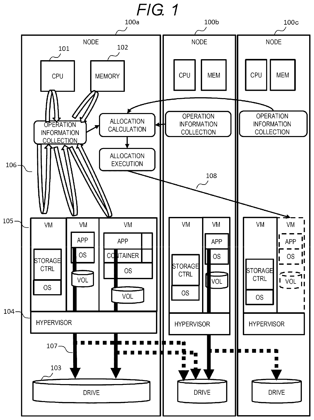
[0052]FIG. 1 is a schematic explanatory diagram of an overall configuration of a system. In each node 100, a hypervisor 104 is operated, such that virtual computers (virtual machines VM) are created in a physical node, and a plurality of different OSs are executed in parallel within the same physical node 100.
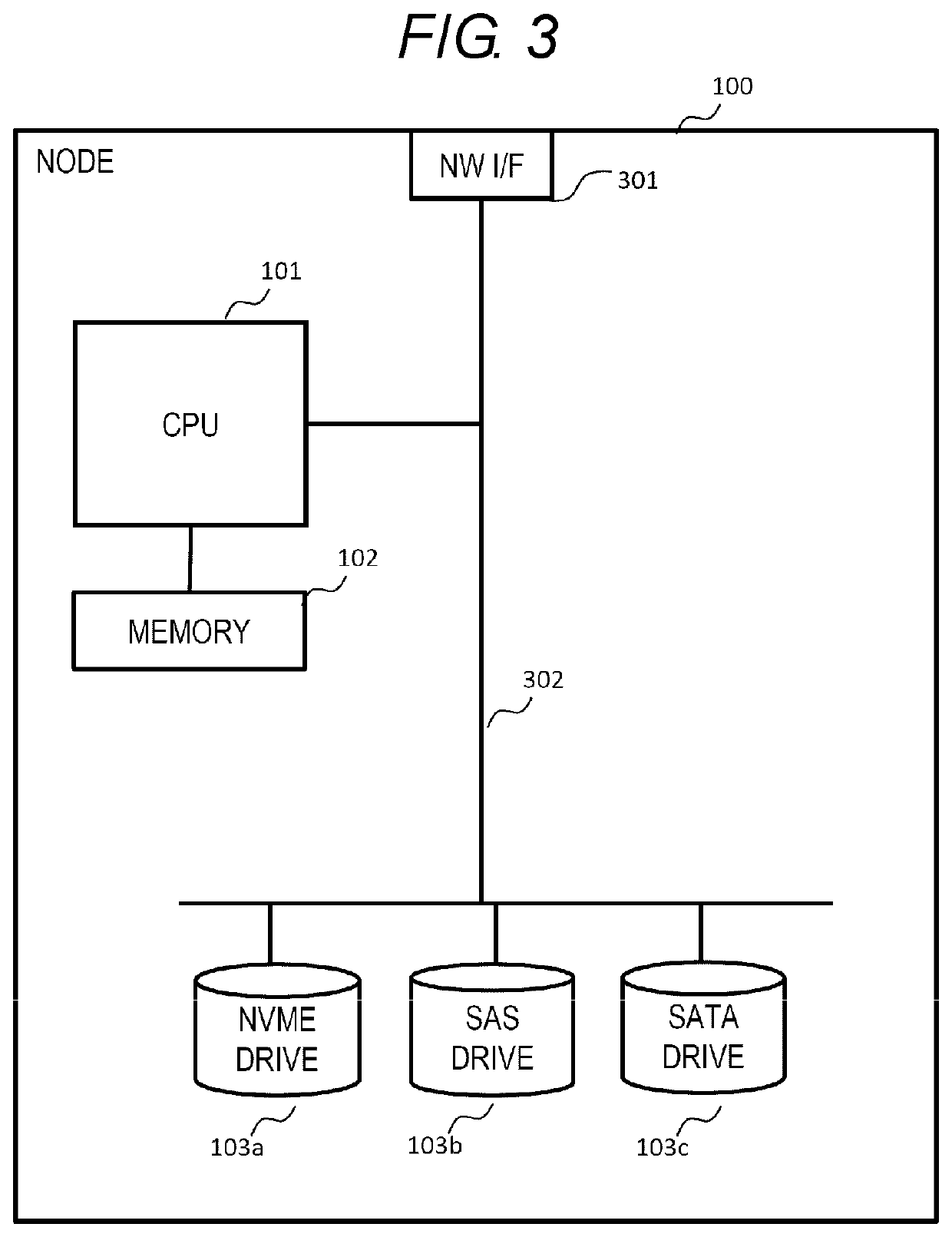
[0053]First, the configuration of the system operated in Example 1 will be described. The system includes a plurality of nodes 100, and each node 100 includes computer resources such as a CPU 101, a memory 102, and a drive 103 serving as a storage device. An environment in which Example 1 is implemented is a so-called hyperconverged infrastructure (HCI) environment, known as a virtual infrastructure that integrates co...
example 2
[0152]FIG. 18 is a flow diagram of determining allocation of a VM / container or volume when a node failure occurs according to Example 2. The processing shown in FIG. 18 is executed by the storage management program 502 of the management unit, and can be understood as a modification of the processing in FIG. 15 of Example 1. This processing is a case where a VM / container operating at a node, in which a failure occurs, is made redundant again due to certain node failures. A case is considered as an example: there is a VM / container in which two redundant applications are operated at three nodes (N1, N2, N3) among five nodes (N1, N2, N3, N4, N5), when a failure occurs in N1, the applications are made redundant again somewhere in N2 to N5.
[0153]In the processing of FIG. 15 of Example 1, the assumed IO amount, the capacity, and the number of the VM / container to be newly created are input by the user in S1501. In contrast, the assumed IO amount, the capacity, and the number to be created o...
example 3
[0155]FIG. 19 shows a configuration according to Example 3 in which two storage VMs (two storage controllers 1901 and 1902 configured in one storage VM) are configured in two different nodes, and a pair is formed by two storage controllers (1901 and 1903) in each node.
[0156]Storage controllers (1901 and 1904) form a redundant configuration (redundant configuration between active and standby) between nodes. An active storage controller (1901) is always operated on at least one node. This example shows an example of active / standby.
[0157]When a failure occurs in a certain node, a standby storage controller corresponding to an active storage controller is promoted to an active storage controller to continue an IO processing (this is referred to as a failover). In the example of FIG. 19, when a failure occurs in a node 2 (100b), an active storage controller 2 is stopped, a standby storage controller 2 of a node 3 (100c) is promoted to active, and a processing of the active storage contro...
PUM
 Abstract
Description
Claims
Application Information
 - R&D
- Intellectual Property
- Life Sciences
- Materials
- Tech Scout
- Unparalleled Data Quality
- Higher Quality Content
- 60% Fewer Hallucinations
Browse by: Latest US Patents, China's latest patents, Technical Efficacy Thesaurus, Application Domain, Technology Topic, Popular Technical Reports.
© 2025 PatSnap. All rights reserved.Legal|Privacy policy|Modern Slavery Act Transparency Statement|Sitemap|About US| Contact US: help@patsnap.com