Antenna

a technology of antennas and conductors, applied in the field of antennas, can solve the problems of difficult to achieve the desired characteristics, difficult to realize the shape of the reflector conductor suitable for two frequencies, and complex overall shape of the antenna

Active Publication Date: 2020-04-02
MURATA MFG CO LTD
View PDF0 Cites 3 Cited by
  • Summary
  • Abstract
  • Description
  • Claims
  • Application Information

AI Technical Summary

Benefits of technology

[0026]In this configuration, an array antenna is formed, and the distances from the plurality of parasitic elements to the ground conductor for a radio frequency signal of the se

Problems solved by technology

Because of this, the overall shape of the antenna becomes complex, and it is not easy to achieve the desired characteristics.
Further, in a case where the antenna describe

Method used


Image

  • Antenna
  • Antenna
  • Antenna

Examples


Embodiment Construction

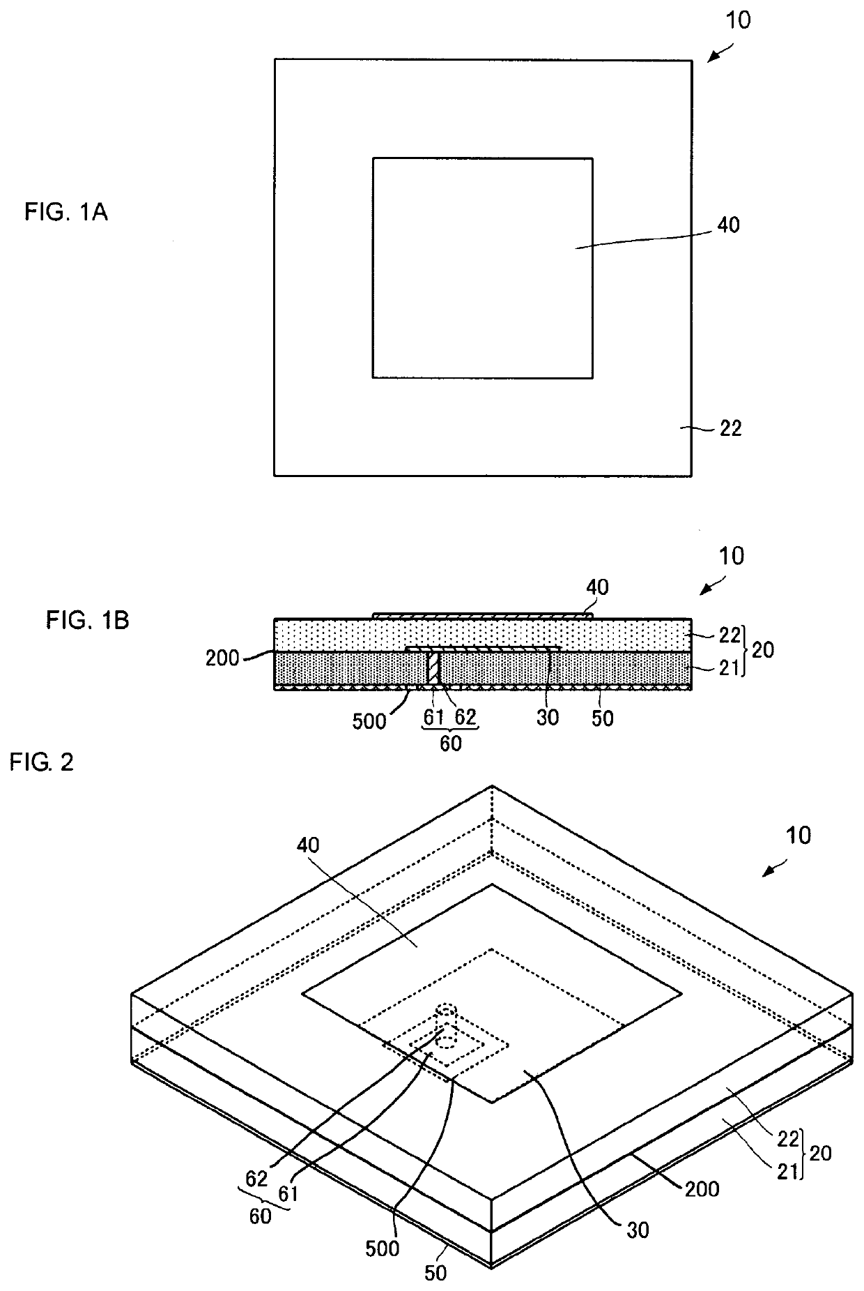
[0038]An antenna according to a first embodiment of the present disclosure is described with reference to the drawings. FIG. 1A is a plan view of an antenna 10 according to the first embodiment of the present disclosure, and FIG. 1B is a side cross-sectional view of the antenna 10. FIG. 2 is an external perspective view of the antenna 10 according to the first embodiment of the present disclosure.

[0039]As illustrated in FIG. 1A, FIG. 1B, and FIG. 2, the antenna 10 includes a dielectric substrate 20, a radiating element 30, a parasitic element 40, a ground conductor 50, and a feed conductor 60.

[0040]The dielectric substrate 20 is rectangular in the plan view. The dielectric substrate 20 includes a first dielectric layer 21 and a second dielectric layer 22. The first dielectric layer 21 and the second dielectric layer 22 are both a rectangular flat film in the plan view. The first dielectric layer 21 and the second dielectric layer 22 are stacked on top of each other in such a way tha...


PUM


Abstract

An antenna includes a dielectric substrate, a radiating element, a parasitic element, and a ground conductor. The dielectric substrate has a plate-like shape having a top face and a back face opposite to each other. The radiating element is placed between the top face and the back face of the dielectric substrate and transmits and receives a radio frequency signal of a first frequency. The parasitic element is placed on the top face of the dielectric substrate and transmits and receives a radio frequency signal of a second frequency. The ground conductor is placed on the back face of the dielectric substrate. The second frequency is a lower frequency than the first frequency. The dielectric substrate has an electric field boundary plane that reflects a radio frequency signal of the second frequency at an intermediate position in a thickness direction orthogonal to the top face and the back face.

Description

[0001]This is a continuation of International Application No. PCT / JP2018 / 020132 filed on May 25, 2018 which claims priority from Japanese Patent Application No. 2017-111465 filed on Jun. 6, 2017. The contents of these applications are incorporated herein by reference in their entireties.BACKGROUND OF THE DISCLOSUREField of the Disclosure[0002]The present disclosure relates to an antenna that transmits and receives a plurality of radio frequency signals of different frequencies.Description of the Related Art[0003]In general, as antennas for mobile communication terminals and the like, various kinds of small-size antenna devices are put to practical use. For example, patent document 1 and patent document 2 each describe a patch antenna including a radiating element being fed with a radio frequency signal by a conductor and a parasitic element that uses electromagnetic coupling.[0004]In an antenna described in the patent document 1, the parasitic element forms a loop-like slot antenna....

Claims


Application Information

Patent Timeline
IPC IPC(8): H01Q5/378H01Q1/38H01Q1/48H01Q1/24
CPCH01Q1/243H01Q1/38H01Q1/48H01Q5/378H01Q9/0414H01Q21/065
Inventor IZAWA, MASAHIROYAMADA, YOSHIKI
Owner MURATA MFG CO LTD
Why Eureka
Try Eureka