
Motor-Vehicle Auxiliary Ventilation System

Active Publication Date: 2020-04-09
CENT RECERCHE FIAT S PA
View PDF0 Cites 0 Cited by
  • Summary
  • Abstract
  • Description
  • Claims
  • Application Information

AI Technical Summary

Benefits of technology

The invention aims to provide a simple and low-cost system to solve the problem of excessive heat or cold in a motor-vehicle when it is stationary with the engine off and the driver is outside. The system includes an auxiliary refrigeration and / or heating system that can cool or heat the passenger compartment of the vehicle when the engine is turned off and the driver is outside. This improves the comfort of the vehicle and the driver's experience.

Problems solved by technology

In conventional vehicles, the problem arises of enabling activation of a ventilation mode of the passenger compartment of the motor-vehicle when the driver is still outside the motor-vehicle, for example, after the motor-vehicle has remained parked with the engine off for a prolonged time in a high temperature environment and exposed to solar radiation.
In conventional motor-vehicles, activation of a ventilation mode of the passenger compartment before the driver even enters the motor-vehicle would result in the ignition of the internal combustion engine, but this operating condition is generally prohibited by current legislations in various countries, unless the vehicle is an electric or hybrid vehicle.
For vehicles equipped with an internal combustion engine, the problem arises of activating the aforesaid operating modes without requiring ignition of the internal combustion engine.

Method used


Image

  • Motor-Vehicle Auxiliary Ventilation System
  • Motor-Vehicle Auxiliary Ventilation System
  • Motor-Vehicle Auxiliary Ventilation System

Examples


first embodiment

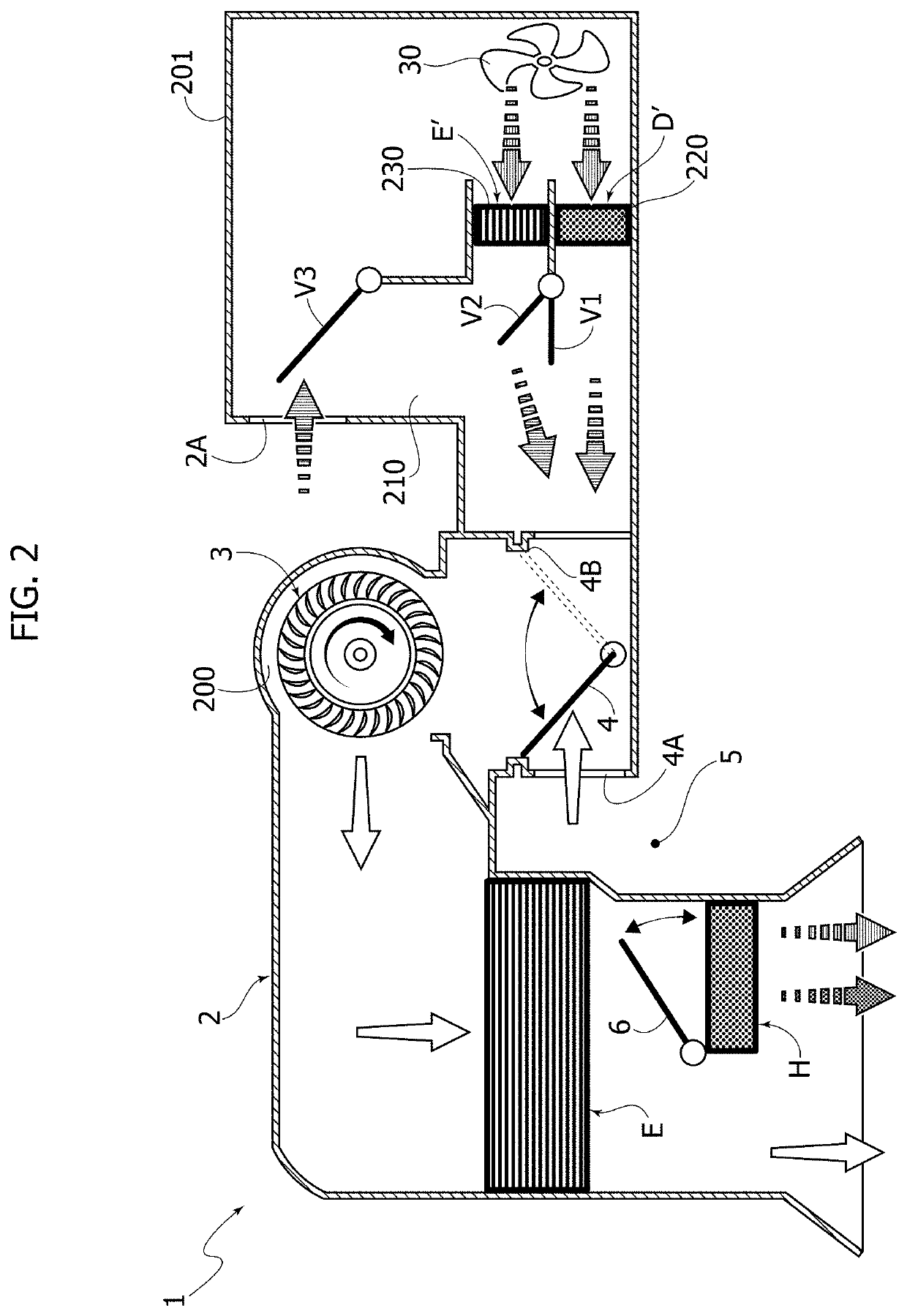
[0012]FIG. 2 illustrates the assembly of FIG. 1 modified

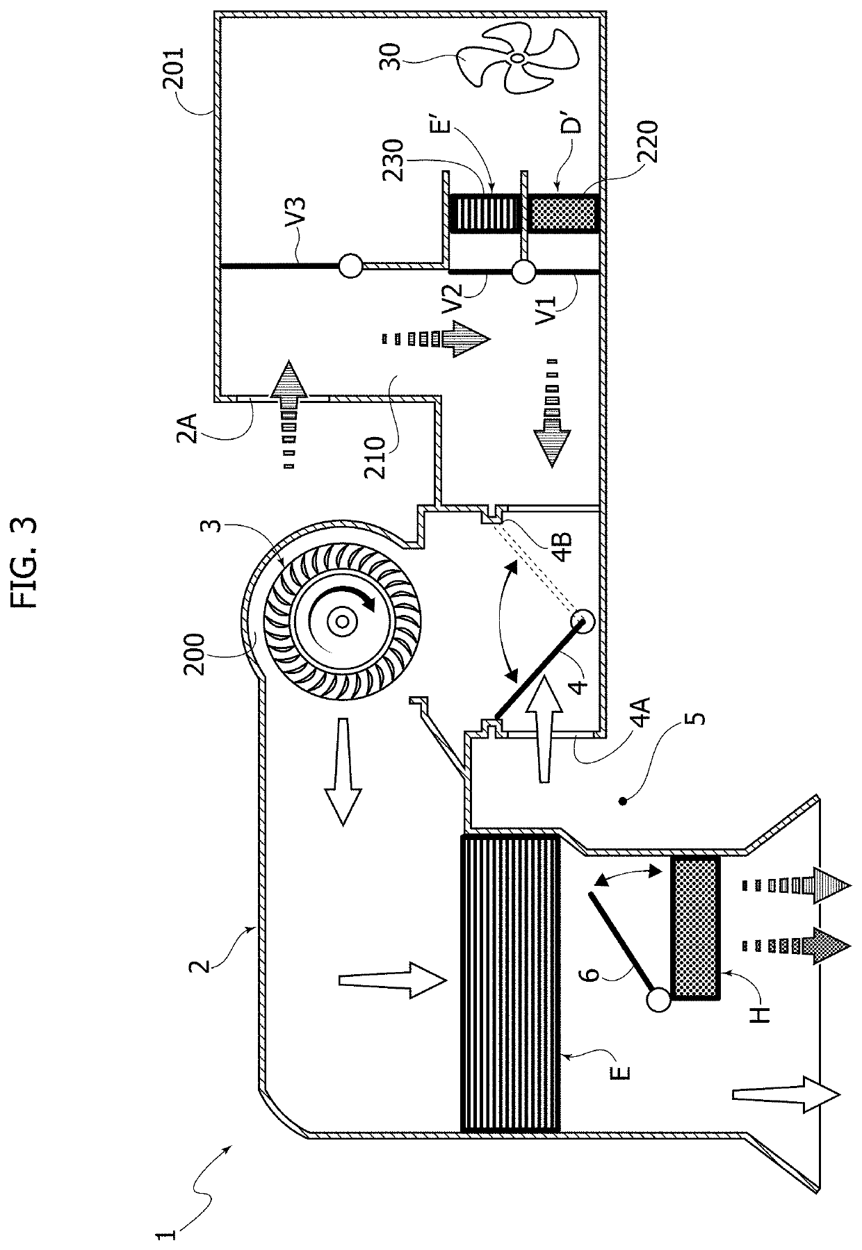
[0013]FIGS. 3-5 illustrate three different operating conditions of the assembly of FIG. 2,

[0014]FIG. 6 is a schematic view of the main refrigeration circuit and of the auxiliary refrigeration circuit,

[0015]FIGS. 7-9 are schematic views illustrating different operating conditions of two valves for controlling the flow of air to the condenser and to the evaporator of the auxiliary refrigeration circuit,

[0016]FIG. 10 is a schematic view of a motor-vehicle equipped with a system according to the invention for activating the natural circulation of air through the passenger compartment of the motor-vehicle, according to the disclosures of the present invention,

[0017]FIG. 11 is a perspective view of a pair of shutters forming part of the system illustrated in FIG. 10,

[0018]FIG. 12 illustrates a flow chart relating to an example of control methods of a preferred embodiment of the system according to the invention,

second embodiment

[0019]FIG. 13 illustrates a variant of FIG. 2, corresponding to a

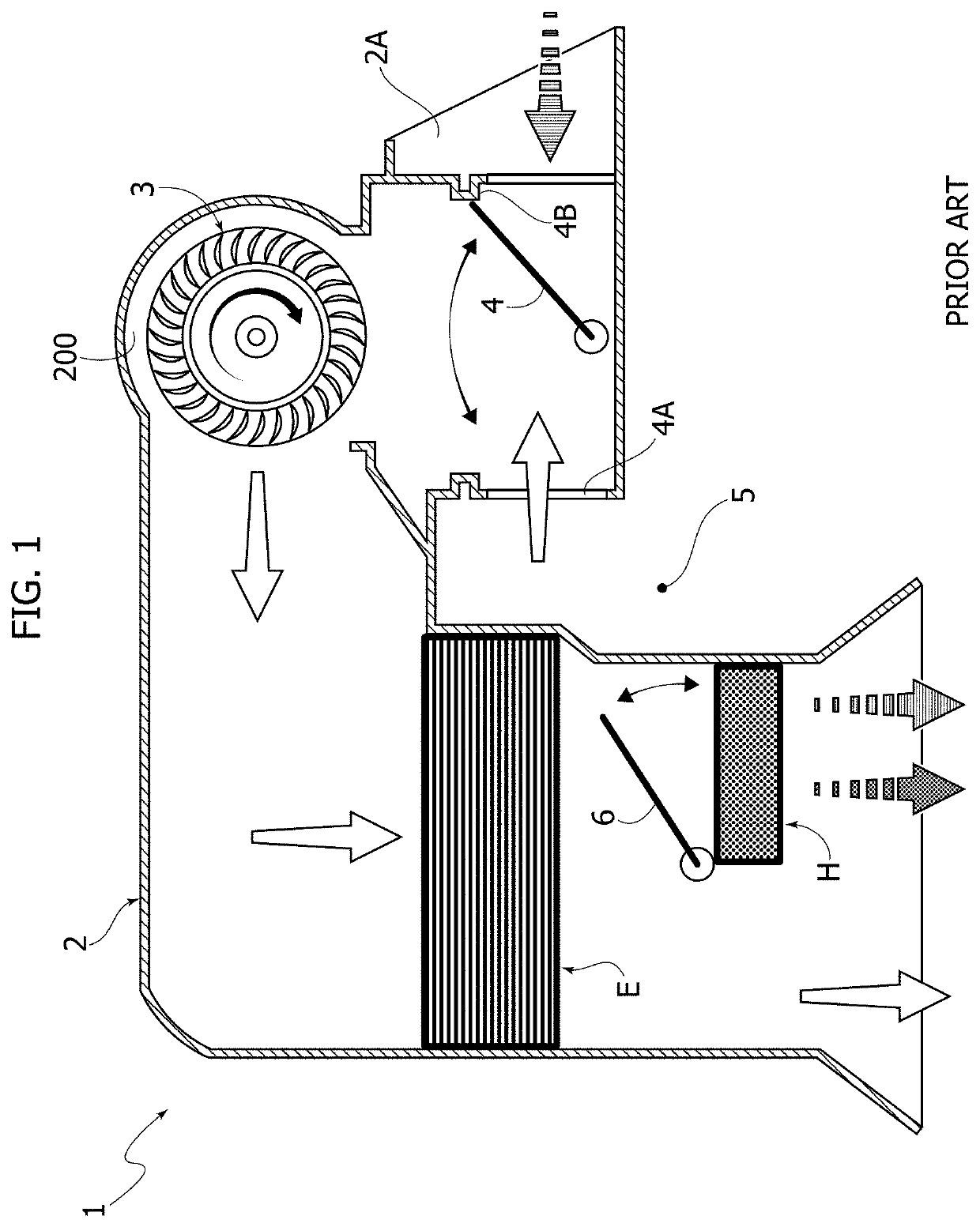
[0020]In FIG. 1, numeral 1 indicates—in its entirety—a HVAC assembly of Heating, Ventilation and Air Conditioning of a motor-vehicle according to the conventional art. The assembly 1 includes an air guide duct indicated—in its entirety—with the reference 2, having an inlet opening 2A for the entry into the duct 2 of an air flow drawn from the external environment by means of an electrically-operated fan 3 located inside the duct 2. A shutter valve 4 is interposed between the inlet opening 2A and the fan 3, which connects the portion of the duct 2 in which the valve 3 is arranged selectively with the inlet opening 2A (when it is required to activate a flow of air from the outside into the duct 2) or with an opening 4A for communication of the duct 2 with the environment 5 inside the passenger compartment of the motor-vehicle (when it is required to recirculate the air of the passenger compartment in the duct). In FIG. 1...


PUM


Abstract

A motor-vehicle includes one or more electrically-operated valves, arranged on the structure of the motor-vehicle in a lower position with respect to the windows, for providing a communication between a passenger compartment and the external environment, and one or more electronic control units programmed to activate a ventilation mode of the passenger compartment when the motor-vehicle is parked with the engine off, even with the driver outside the vehicle. The ventilation mode includes controlling at least partial opening of one or more windows and the opening of one or more of the valves to generate a flow of natural air from the bottom upwards through the passenger compartment of the motor-vehicle.

Description

FIELD OF THE INVENTION[0001]The present invention relates to systems for ventilating the passenger compartment of a motor-vehicle.PRIOR ART[0002]In conventional vehicles, the problem arises of enabling activation of a ventilation mode of the passenger compartment of the motor-vehicle when the driver is still outside the motor-vehicle, for example, after the motor-vehicle has remained parked with the engine off for a prolonged time in a high temperature environment and exposed to solar radiation. In conventional motor-vehicles, activation of a ventilation mode of the passenger compartment before the driver even enters the motor-vehicle would result in the ignition of the internal combustion engine, but this operating condition is generally prohibited by current legislations in various countries, unless the vehicle is an electric or hybrid vehicle. For vehicles equipped with an internal combustion engine, the problem arises of activating the aforesaid operating modes without requiring...

Claims


Application Information

Patent Timeline
IPC IPC(8): B60H1/00B60H1/24B60H1/26
CPCB60H1/26B60H1/00849B60H1/241B60H2001/3485B60H1/00357B60H1/00485B60H1/00657B60H1/00771B60H1/00778B60H1/248B60H1/323B60H2001/00085B60H2001/00099B60H2001/00949E05F15/71E05Y2800/414E05Y2800/75
Inventor FERRARIS, WALTERBETTOJA, FEDERICAMATTIELLO, FABRIZIOLAZZARO, PIETROCARZANA, ANDREA
Owner CENT RECERCHE FIAT S PA
Learn More