
Device for adjusting a retrograde timepiece display

a technology of retrograde timepieces and display mechanisms, applied in the field of retrograde timepiece display mechanisms, can solve the problems of inaccurate retrograde display mechanisms that utilise cams and sensing fingers, inconvenience for users, and inability to adjust the display

Active Publication Date: 2020-04-16
BLANCPAIN SA
View PDF0 Cites 5 Cited by
  • Summary
  • Abstract
  • Description
  • Claims
  • Application Information

AI Technical Summary

Benefits of technology

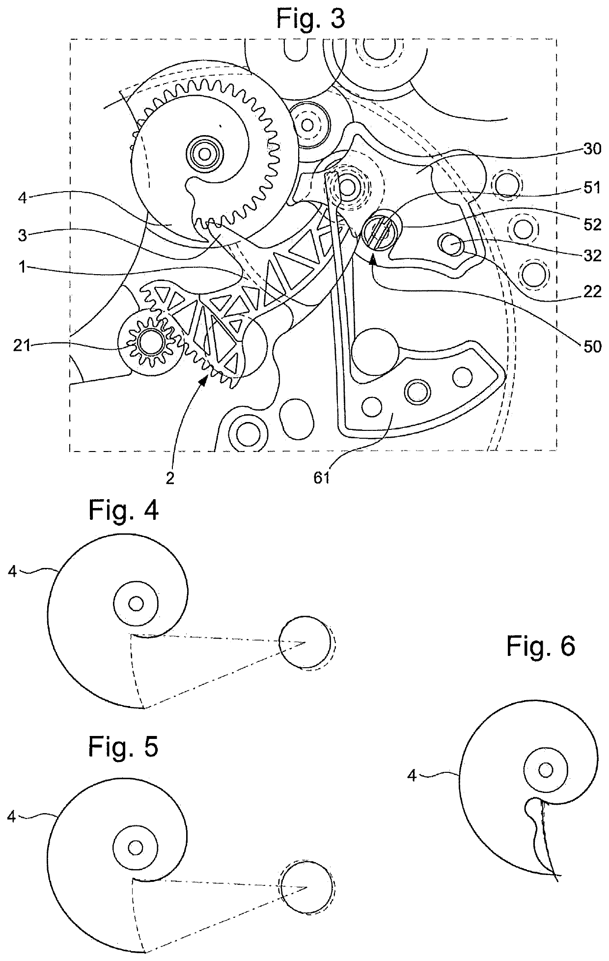
The invention proposes a simple adjustment system that can compensate for manufacturing inaccuracies of components by making a slight shift of the pivot centre of the sensing rack and / or of the cam. This allows for a + / −4° adjustment on the retrograde display, which is necessary to ensure accurate and reliable functioning of the system. The high reduction ratio between the sensing rack and the display pinion makes the adjustment possible.

Problems solved by technology

Retrograde display mechanisms that utilise a cam and a sensing finger are, by design, inaccurate.
Indeed, the inaccuracy depends on the gear ratio between the sensing rack and the display pinion.
It is thus possible that the display initially intended for an angular sector of 270′, only appears on an angular sector of 266° or 274°, which is noticeable, and unpleasant for the user, since the optical effect may be further amplified by the design of the dial.

Method used


Image

  • Device for adjusting a retrograde timepiece display
  • Device for adjusting a retrograde timepiece display
  • Device for adjusting a retrograde timepiece display

Examples


Embodiment Construction

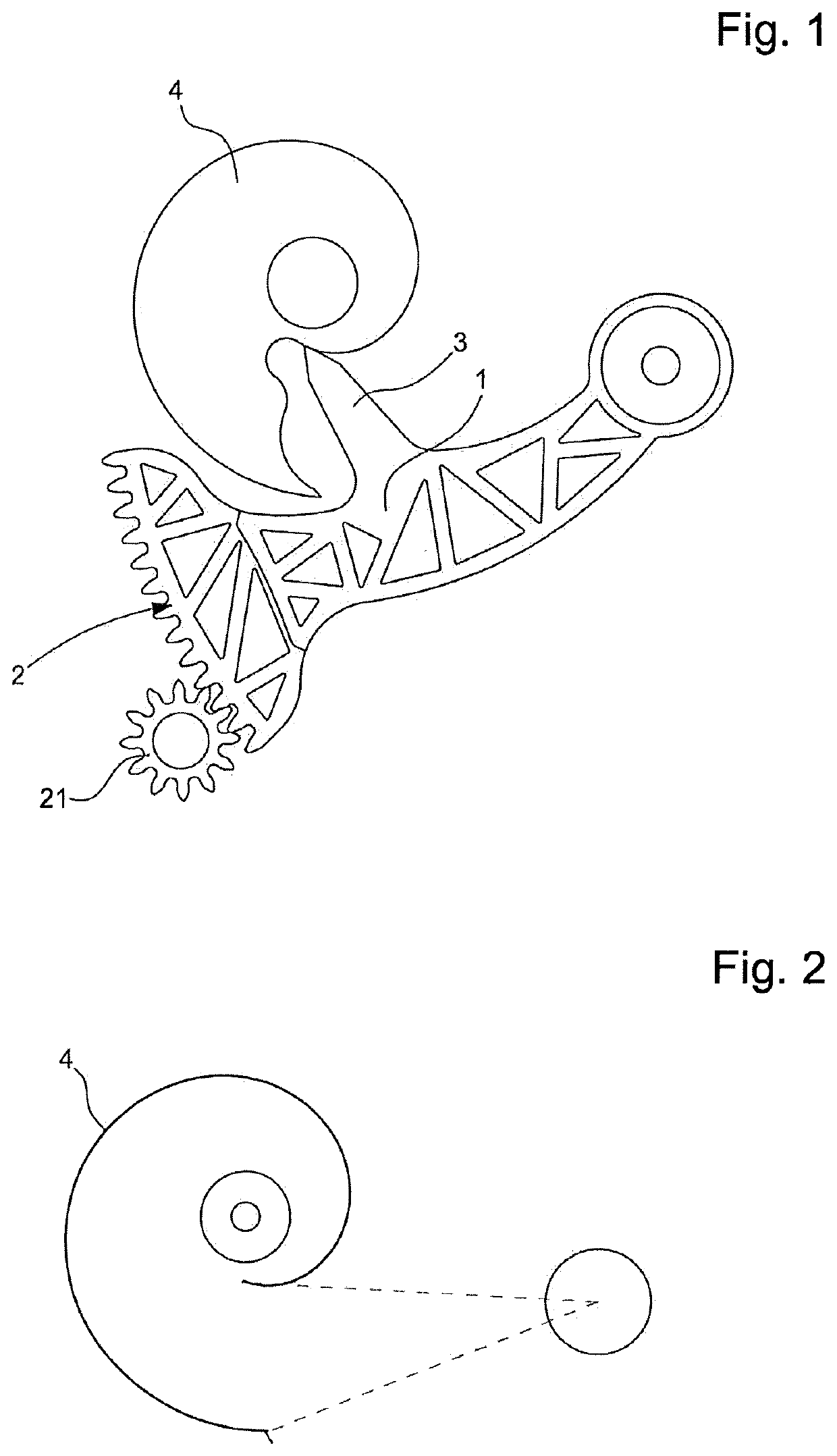
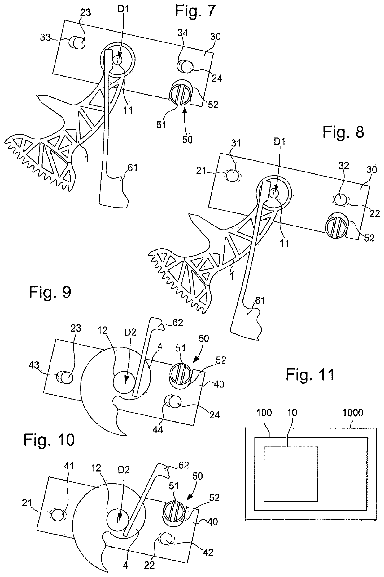
[0024]The invention concerns a retrograde timepiece display mechanism 10, comprising a main plate 20 and at least one sensing rack 1. This rack 1 is pivotally mounted on a first arbor 11 pivoting about a first pivot axis D1, and includes a toothing 2 centred on this first pivot axis D1. Rack 1 includes a sensing finger 3, which is arranged to follow the periphery of a cam 4, comprised in this retrograde display mechanism 10, and which is pivotally mounted on a second arbor 12 pivoting about a second pivot axis D2. Toothing 2 of rack 1 is arranged to drive a display pinion 21, which carries or drives a display member such as a hand or similar, not represented in the Figures.

[0025]In the non-limiting example illustrated by the Figures, the reduction ratio between the sensing rack and the display pinion is 130 / 12. A total theoretical angle of the rack of 24.929° corresponds to a theoretical angle of 270.06° on the display pinion. Naturally, if through the manufacturing process, minimal...


PUM


Abstract

A retrograde display mechanism including a main plate and a rack pivoting on a first arbor about a first axis centring its toothing, and including a sensing element following a cam pivoting on a second arbor about a second axis, the position of the first pivot axis and / or of the second pivot axis is adjustable with respect to the main plate with an adjustment plate carrying the first arbor and / or respectively the second arbor, and movable with at least one degree of freedom with respect to the main plate whose position with respect to the main plate is adjustable by an adjustment control device or an eccentric screw secured to the main plate and cooperating with a notch in the adjustment plate, or vice versa.

Description

FIELD OF THE INVENTION[0001]The invention concerns a retrograde timepiece display mechanism, comprising a main plate and at least one rack pivotally mounted on a first arbor pivoting about a first pivot axis and comprising a toothing centred on said first pivot axis, which rack includes a sensing finger arranged to follow the periphery of a cam comprised in said retrograde display mechanism and which is pivotally mounted on a second arbor pivoting about a second pivot axis.[0002]The invention also concerns a timepiece movement including at least one such retrograde display mechanism.[0003]The invention also concerns a timepiece, especially a watch, including at least one such retrograde display mechanism.[0004]The invention concerns the field of timepiece display mechanisms, and more specifically the field of retrograde display mechanisms.BACKGROUND OF THE INVENTION[0005]Retrograde display mechanisms that utilise a cam and a sensing finger are, by design, inaccurate. Indeed, the ina...

Claims


Application Information

Patent Timeline
IPC IPC(8): G04B19/02G04B19/04
CPCG04B19/04G04B19/02G04B19/00G04B19/082G04B35/00
Inventor DENDEN, MEHDI
Owner BLANCPAIN SA
Learn More