Intake device for internal combustion engine

Active Publication Date: 2020-04-23
TOYOTA JIDOSHA KK
View PDF9 Cites 2 Cited by
  • Summary
  • Abstract
  • Description
  • Claims
  • Application Information

AI Technical Summary

Benefits of technology

The patent text describes a configuration for an intake system of an engine that includes a partition plate. The partition plate is located in the connection pipe that connects the surge tank and is positioned in the straight portion of the connection pipe. The intake air flows through the connection pipe and is directed towards the rotation axis of the crankshaft. This helps to reduce disturbance of the air flow and allows the air to flow easily into the surge tank. The partition plate also helps to reduce concentration of the air flow on the outer side of the curved flow passage in the connection pipe, which improves the flow of the air. Additionally, the patent describes how the partition plate helps to reduce disturbance of the air flow when the throttle valve is opened and closed, which improves engine performance.

Problems solved by technology

If separation of the flow of intake air flowing through the connection pipe disturbs the flow of the intake air when flowing into the surge tank, pressure loss in the surge tank may be increased.
More specifically, disturbance of the flow of intake air flowing through the connection pipe into the surge tank is limited.

Method used


Image

  • Intake device for internal combustion engine
  • Intake device for internal combustion engine
  • Intake device for internal combustion engine

Examples


first embodiment

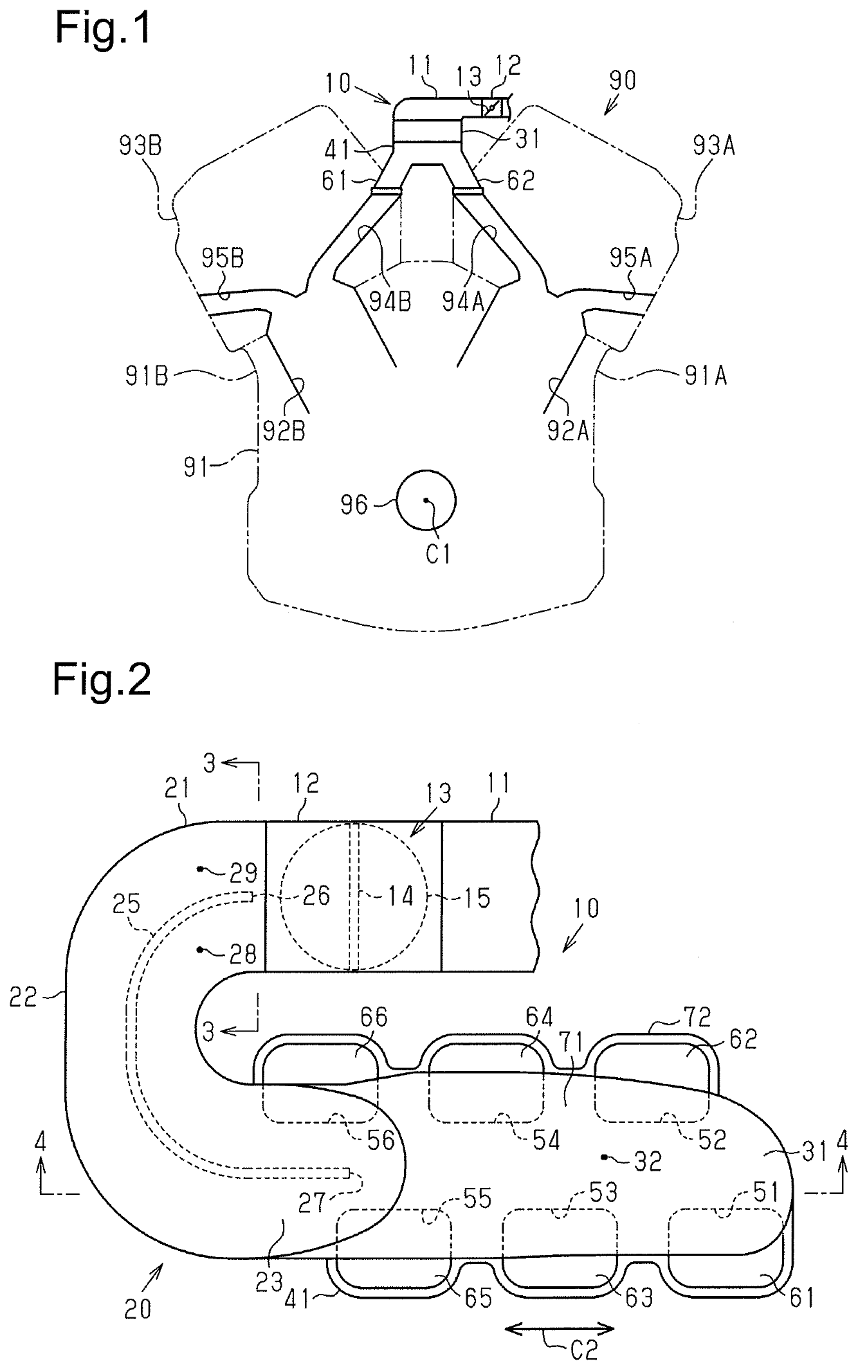
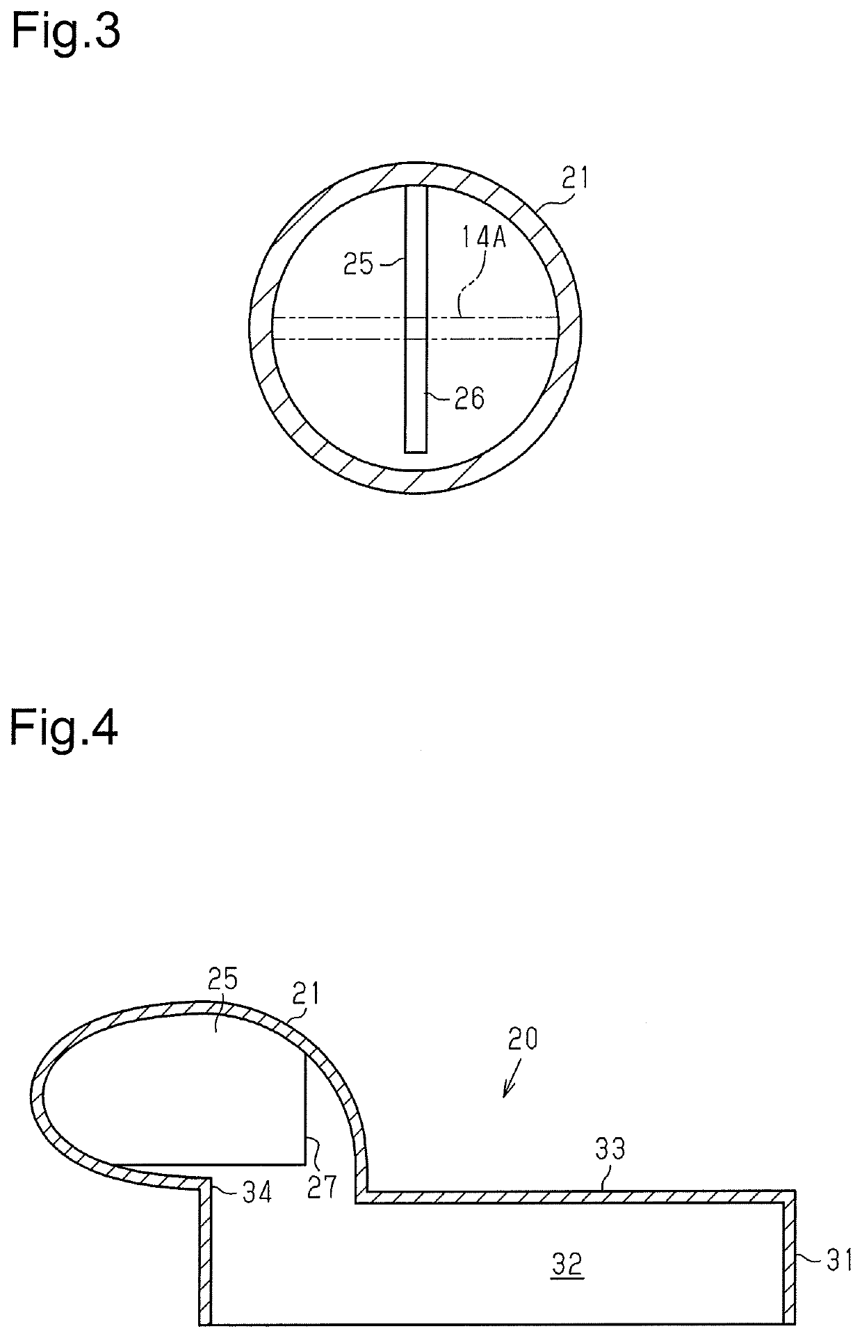
[0048]A first embodiment of an intake device for an internal combustion engine, which is referred to as an intake device 10, will now be described with reference to FIGS. 1 to 4.

[0049]FIG. 1 shows an internal combustion engine 90 including the intake device 10. The internal combustion engine 90 includes a right cylinder group arranged on a right bank 91A of a cylinder block 91 and a left cylinder group arranged on a left bank 91B of the cylinder block 91. The right bank 91A and the left bank 91B are located at opposite sides of a crankshaft 96 of the internal combustion engine 90. In each of the right bank 91A and the left bank 91B, three cylinders are arranged in an extension direction of the rotation axis of the crankshaft 96. The cylinders having cylinder numbers of “#2,”“#4,” and “#6” and configuring the right cylinder group are arranged in the right bank 91A. The cylinders having cylinder numbers of “#1,”“#3,” and “#5” and configuring the left cylinder group are arranged in the...

second embodiment

[0083]A second embodiment of an intake device 210 will now be described with reference to FIGS. 7 and 8.

[0084]In the intake device 10 of the first embodiment, the partition plate 25, which divides the flow passage configured by the connection pipe 21, extends through the center of the cross section of the flow passage in the connection pipe 21. The intake device 210 of the second embodiment differs from the first embodiment in that a partition plate extends through a position deviated from the center of the cross section of the flow passage in the connection pipe. The same reference characters are given to those elements that are the same as the corresponding elements of the first embodiment. Such elements will not be described in detail.

[0085]FIG. 7 shows the intake device 210. The intake device 210 includes a surge tank unit 220 including a connection pipe 221 that connects the throttle body 12 and the tank 31. The connection pipe 221 includes a U-shaped curved portion 222. The cu...

third embodiment

[0094]A third embodiment of an intake device 310 will now be described with reference to FIGS. 9 and 10.

[0095]The intake device 310 differs from the intake device 10 of the first embodiment and the intake device 210 of the second embodiment in that the intake device 310 includes a first partition plate 331 and a second partition plate 337 as partition plates that divide the flow passage in a connection pipe 321. The same reference characters are given to those elements that are the same as the corresponding elements of the first embodiment. Such elements will not be described in detail.

[0096]As shown in FIGS. 9 and 10, the intake device 310 includes the connection pipe 321 connecting the tank 31 and the throttle body 12. FIG. 9 shows a cross-sectional structure of connection portions of the throttle body 12 and the connection pipe 321.

[0097]The connection pipe 321 is configured by multiple housings in the same manner as the connection pipe 221 of the intake device 210 of the second ...


PUM


Abstract

An intake device for an internal combustion engine configures a flow passage for intake air that is drawn into combustion chambers. The intake device includes an intake manifold configuring multiple runners that respectively distribute intake air to multiple cylinders, a surge tank including a cavity that is connected to the runners and defines a convergence portion, a throttle body incorporating a throttle valve, and a connection pipe connecting the surge tank and the throttle body and configuring a curved flow passage extending between the throttle body and the surge tank. The connection pipe includes a partition plate that divides the curved flow passage into a circumferentially inner flow passage and a circumferentially outer flow passage.

Description

1. FIELD[0001]The following description relates to an intake device for an internal combustion engine.2. DESCRIPTION OF RELATED ART[0002]An intake device for an internal combustion engine having multiple cylinders includes an intake manifold that distributes intake air to each cylinder. A surge tank is provided at an upstream side of the intake manifold to temporarily store the intake air.[0003]Japanese Laid-Open Patent Publication No. 2016-156350 discloses an intake device for an internal combustion engine. The intake device includes a connection pipe connecting the surge tank to a throttle body arranged at an upstream side of the surge tank. The flow of intake air that has passed through the throttle body is curved by the connection pipe, and the intake air is drawn into the surge tank.[0004]When intake air flows through a flow passage that is curved like the above connection pipe, the flow of the intake air may be separated from the inner wall of the connection pipe. More specifi...

Claims


Application Information

Patent Timeline
IPC IPC(8): F02M35/104F02M35/10
CPCF02M35/10262F02M35/10072F02M35/116F02M35/1045F02M35/10052F02M35/10019F02M35/10032F02M35/10111Y02T10/12
Inventor IBARAGI, TADASHINAKAYAMA, KAZUAKIITOH, AKOKOIKE, RYUJIKONDO, TOSHIYUKI
Owner TOYOTA JIDOSHA KK
Why Eureka
Try Eureka