Multi-Purpose Tile System, Tile Covering, and Tile

a multi-purpose tile and tile technology, applied in the field of multi-purpose tile systems, can solve the problems of subsequent changes, floor panels themselves can drift apart, and the tiles themselves are not easy to be rearranged, so as to improve the acoustic (sound-dampening) properties of tiles, reduce porosity, and improve the overall density of the core layer

Active Publication Date: 2020-04-30
I4F LICENSING NV
View PDF16 Cites 15 Cited by
  • Summary
  • Abstract
  • Description
  • Claims
  • Application Information

AI Technical Summary

Benefits of technology

[0066]The density of the base layer preferably varies along the height of the base layer. This may positively influence the acoustic (sound-dampening) properties of the tiles as such. Preferably, at a top section and/or a bottom section of a foamed base layer a crust layer may be formed. This at least one crust layer may form integral part of the base layer. More preferably, both the top section and the bottom section of the base layer form a crust layer enclosing the foam structure. The crust layer is a relatively closed (reduced porosity, preferably free of bubbles (cells)), and hence forms a relatively rigid (sub)layer, compared to the more porous foam structure. Commonly, though not necessary, the crust layer is formed by sealing (searing) the bottom and top surface of the core layer. Preferably the thickness of each crust layer is between 0.01 and 1 mm, preferably between 0.1 and 0.8 mm. A too thick crust will lead to a higher average density of the core layer which increases both the costs and the rigidity of the core layer. The thickness of the base layer (core layer) as such is preferably between 2 and 10 mm, more preferably between 3 and 8 mm, and is typically approximately 4 or 5 mm. Preferably, a top section and/or a bottom section of the (composite) base layer forms a crust layer having a porosity which is less than the porosity of the closed cell foam plastic material of the base layer, wherein the thickness of each crust layer is preferably between 0.01 and 1 mm, preferably between 0.1 and 0.8 mm.
[0067]Preferably, each tile comprises at least one backing layer affixed to a bottom side of the base layer, wherein said at least one backing layer at least partially made of a flexible material, preferably an elastomer. The thickness of the backing layer typically varies from about 0.1 to 2.5 mm. Non-limiting examples of materials whereof the backing layer can be made of are polyethylene, cork, polyurethane and ethylene-vinyl acetate. The thickness of a polyethylene backing layer is for example typically 2 mm or smaller. The backing layer commonly provides additional robustness and impact resistances to each tile ...

Problems solved by technology

This technique has a disadvantage that is rather complicated and that subsequent changes can only be made by breaking out the floor panels.
A disadvantage with a floor covering of the above-mentioned type, above all, if the floor panels are installed loosely onto the subflooring, consists in that during the expansion of the ...

Method used


Image

  • Multi-Purpose Tile System, Tile Covering, and Tile
  • Multi-Purpose Tile System, Tile Covering, and Tile
  • Multi-Purpose Tile System, Tile Covering, and Tile

Examples


Embodiment Construction

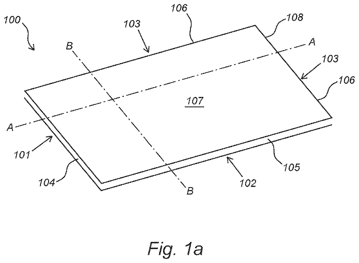
[0235]FIG. 1a shows a schematic representation of a multi-purpose tile (100) for use in a multi-purpose tile system (110) according to the invention. The figure shows a tile (100) comprising a first pair of opposing edges consisting of a first edge (101) and an opposite other edge (103) and a second pair of opposing edges consisting of a second edge (102) and an opposing other edge (103). The first, second and other edges (101, 102, 103) are respectively provided with first, second and third coupling profiles (104, 105, 106). The first coupling profile (104) and the third coupling profile (106) are configured such that two of such tiles (100) can be coupled to each other at the first and other edges (101, 103) by means of a turning movement. Moreover, the second coupling profile (105) and the third coupling profile (106) are configured such that the two of such tiles (100) can be coupled to each other at the second and other edges (102, 103) by means of a fold-down movement and / or a...


PUM

PropertyMeasurementUnit
Timeaaaaaaaaaa
Angleaaaaaaaaaa
Angleaaaaaaaaaa

Abstract

The invention relates to a multi-purpose tile system, in particular a floor tile system, comprising a plurality of multi-purpose tiles, in particular floor tiles, wall tiles, or ceiling tiles. The invention also relates to a tile covering, in particular floor covering, ceiling covering, or wall covering, consisting of mutually coupled tiles according to the invention. The invention further relates to a tile for use in multi-purpose tile system according to the invention.

Description

CROSS-REFERENCE TO RELATED APPLICATION[0001]This application claims priority to Dutch Patent Application No. 2021885 filed Oct. 26, 2018, the disclosure of which is hereby incorporated in its entirety by reference.BACKGROUND OF THE INVENTION1. Field of the Invention[0002]The invention relates to a multi-purpose tile system, in particular a floor tile system, comprising a plurality of multi-purpose tiles, in particular floor tiles, wall tiles, or ceiling tiles. The invention also relates to a tile covering, in particular floor covering, ceiling covering, or wall covering, consisting of mutually coupled tiles according to the invention. The invention further relates to a tile for use in multi-purpose tile system according to the invention. The invention moreover relates to an installation method for installing the system according to the invention to create a tile covering.2. Discussion of the Related Art[0003]The last decade has seen enormous advance in the market for laminate for ha...

Claims


Application Information

Patent Timeline
IPC IPC(8): E04F13/08E04F15/02
CPCE04F15/02038E04F2201/0153E04F2201/0138E04F13/0894E04F15/02E04F15/10E04F15/105E04F15/107E04F15/181E04F2201/023E04F2201/042E04F2201/043E04F2203/02E04F2203/026E04F2290/04E04F2290/045E04F2201/0169E04F2201/03E04F13/077E04F13/18
Inventor BOUCKÉ, EDDY ALBERIC
Owner I4F LICENSING NV
Why Eureka
Try Eureka