Plasma Generator

a generator and plasma technology, applied in the field of plasma generators, can solve the problems of reducing plasma generation efficiency, excluding plasma entirely, and low edge ignition, so as to achieve simple and reliable system, prevent plasma ignition

Active Publication Date: 2020-04-30
EPCOS AG +1
View PDF0 Cites 3 Cited by
  • Summary
  • Abstract
  • Description
  • Claims
  • Application Information

AI Technical Summary

Benefits of technology

[0005]In order to avoid undesired plasma ignitions at the longitudinal edges of the output region, additional measures are needed. German Patent Application DE 10 2014 110 405 A1 describes, for example, that the output-side longitudinal edges can be rounded or that the output region could be at least partly surrounded by an insulation in order to avoid the undesired plasma ignitions along the edges. The partial insulation of the output region, in particular, damps oscillations of the piezoelectric transformer, with the result that the plasma generation efficiency is reduced. Furthermore, the insulation constitutes a factor that reduces the lifetime of the transformer. Rounding the edges requires additional manufacturing steps that increase the manufacturing outlay.
[0010]As a result of the positioning of a load in front of the output-side end face, the electric field strength of an electric field generated by the piezoelectric transformer can be concentrated on the corners of the output-side end face and the immediate surroundings thereof, with the result that plasma ignitions along the longitudinal edges of the output region can be avoided. If no load is arranged in front of the output-side end face, the electric field generated by the piezoelectric transformer is nondirectional and points in all spatial directions, wherein the field has considerable field components along the longitudinal edges of the output region as well. The load in front of the output-side end face provides for guiding the electric field, with the result that a maximum field strength is attained at the corners of the output-side end face.
[0018]In this way, ignitions of plasma can be prevented as long as no load is positioned in front of the output. The object identification can be carried out, for example, mechanically, optically or on the basis of an impedance or phase measurement at the piezoelectric transformer.
[0019]The device for identifying an object arranged in front of the output-side end face can comprise, for example, a mechanical probe element, which projects beyond the output-side end face in the longitudinal direction. The mechanical probe element can be configured in particular to identify touching of an object and to enable the plasma generation in this case. Such a mechanical probe element constitutes a simple and reliable system for object identification.
[0023]Alternatively or additionally, the device for identifying an object arranged in front of the output-side end face can comprise an optical measuring device. The optical measuring device can be configured to emit an ultrasonic signal, to measure a reflection of the ultrasonic signal and to carry out a distance measurement on the basis of the measured reflection. Devices for optical distance measurement of this type allow a distance measurement with a high precision and can be supplemented in a simple manner as module in the plasma generator.
[0034]The output region of the piezoelectric transformer can be free of an insulation, for example, a shrink-on sleeve. On account of the above-described configuration of the plasma generator in which plasma is generated only if a load is arranged in front of the output-side end face of the transformer, it is possible to dispense with such an insulation in order to avoid undesired plasma ignitions along the longitudinal edges. Such an insulation would result in a damping of the oscillations of the piezoelectric transformer, as a result of which the efficiency would be reduced and the lifetime of the transformer would furthermore be reduced. In an alternative exemplary embodiment, such an insulation of the output region can additionally be provided as a further measure for avoiding undesired plasma ignitions.

Problems solved by technology

The probability of this resulting in ignition along the edges is indeed low, but cannot be entirely ruled out.
The partial insulation of the output region, in particular, damps oscillations of the piezoelectric transformer, with the result that the plasma generation efficiency is reduced.
Furthermore, the insulation constitutes a factor that reduces the lifetime of the transformer.

Method used


Image

  • Plasma Generator
  • Plasma Generator
  • Plasma Generator

Examples


Embodiment Construction

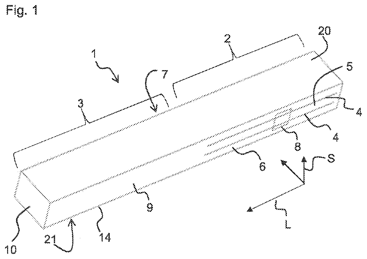
[0081]FIG. 1 shows a piezoelectric transformer 1 in a perspective view. The piezoelectric transformer 1 can be used in particular in a plasma generator for generating non-thermal atmospheric-pressure plasma.

[0082]A piezoelectric transformer 1 is a design of a resonance transformer, which is based on piezoelectricity and constitutes an electromechanical system in contrast to the conventional magnetic transformers. The piezoelectric transformer 1 is a Rosen-type transformer, for example.

[0083]The piezoelectric transformer 1 comprises an input region 2 and an output region 3, wherein the output region 3 is adjacent to the input region 2 in a longitudinal direction L. In the input region 2, the piezoelectric transformer 1 comprises electrodes 4, to which an AC voltage can be applied. The electrodes 4 extend in the longitudinal direction L of the piezoelectric transformer 1. The electrodes 4 are stacked alternately with a piezoelectric material 5 in a stacking direction S, which is perpe...


PUM


Abstract

A plasma generator is disclosed. In an embodiment a plasma generator includes a piezoelectric transformer subdivided into an input region and an output region in a longitudinal direction, wherein the piezoelectric transformer comprises an output-side end face facing away from the input region, wherein the plasma generator comprises a passive load arranged permanently in front of the output-side end face, and wherein the plasma generator is configured to generate non-thermal atmospheric-pressure plasma.

Description

[0001]This patent application is a national phase filing under section 371 of PCT / EP2018 / 056418, filed Mar. 14, 2018, which claims the priority of German patent application 102017105410.3, filed Mar. 14, 2017, each of which is incorporated herein by reference in its entirety.TECHNICAL FIELD[0002]The present invention relates to a plasma generator for generating non-thermal atmospheric-pressure plasma.SUMMARY OF THE INVENTION[0003]Such a plasma generator can comprise a piezoelectric transformer, in particular, which is a design of a resonance transformer which is based on piezoelectricity and constitutes an electromechanical system, in contrast to the conventional magnetic transformers. The piezoelectric transformer can be a Rosen transformer, in particular.[0004]If a piezoelectric transformer is used for generating a non-thermal atmospheric-pressure plasma, then a high voltage is generated in its output region. If the piezoelectric transformer is operated in a gas as load, then it c...

Claims


Application Information

Patent Timeline
Patent Type & Authority Applications(United States)
IPC IPC(8): H05H1/24H01L41/04H01L41/107H01L41/09
CPCH01L41/09H05H2001/2481H01L41/044H05H1/2475H01L41/107H05H1/2481H10N30/20H10N30/40H10N30/804
Inventor NETTESHEIM, STEFANBURGER, DOMINIKHOPPENTHALER, FLORIANWEILGUNI, MICHAELPUFF, MARKUSKUDELA, PAVOL
Owner EPCOS AG
Why Eureka
Try Eureka