Multifuctional hub

Inactive Publication Date: 2020-05-07
YANG CUIFANG
View PDF0 Cites 2 Cited by
  • Summary
  • Abstract
  • Description
  • Claims
  • Application Information

AI Technical Summary

Benefits of technology

The present invention provides a multifunctional hub that solves various problems in the prior art. The hub has a sliding cavity with an upward opening in the box body, and an annular slider is slidably provided in the sliding cavity. A fixed block is fixed on the outer end surface of the ring slider, a grip is fixed on the outer end surface of the fixed block, a locking tooth is fixed on the bottom surface of the box body, and a locking tooth is fixed on the top surface of the box body. A first spring is connected between the surfaces, and a first disk is fixed at the bottom end of the spline shaft. A second spring is connected between the pawl and the top surface of the second disk, and a hydraulic cavity is provided in the bottom wall of the second cavity. A second chute is provided between the hydraulic chamber and the second cavity, a sealing ring is fixed on the outside of the second chute, and a first ejector rod is slidably arranged in the second chute. A magnet block fixedly connected to the first ejector rod is slidingly arranged in the hydraulic chamber, and a fourth spring is connected between the bottom surface of the magnet block and the bottom wall of the hydraulic chamber. The hub has simple and clear operation, sensitive response, and saves time and labor. The device of the present invention is rich in functions, fixed and reliable, and highly practical.

Problems solved by technology

The wires are of different lengths and will be cluttered if they are not organized.
This affects the appearance and is not conducive to replacing or changing the wires.
The wire is manually wound on the hub, and the general hub cannot be fixed, it is easy to move around, rub against the ground, and contaminate the dust; in addition, when the general hub is on the desktop, the function is single and takes up extra space; therefore, it is necessary to design a Multifunctional hub to solve the above problems.

Method used


Image

  • Multifuctional hub
  • Multifuctional hub
  • Multifuctional hub

Examples


Embodiment Construction

[0013]All features disclosed in this specification, or all disclosed methods or steps, other than mutually exclusive features and / or steps, may be combined in any manner.

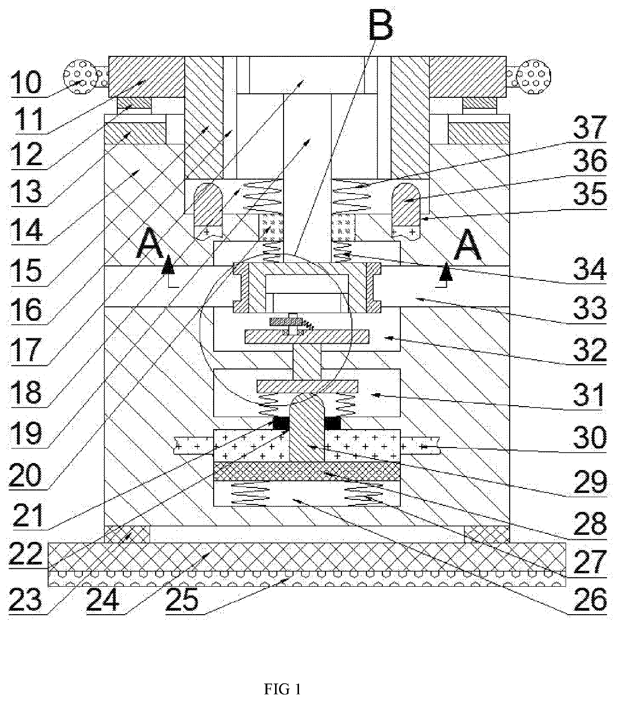
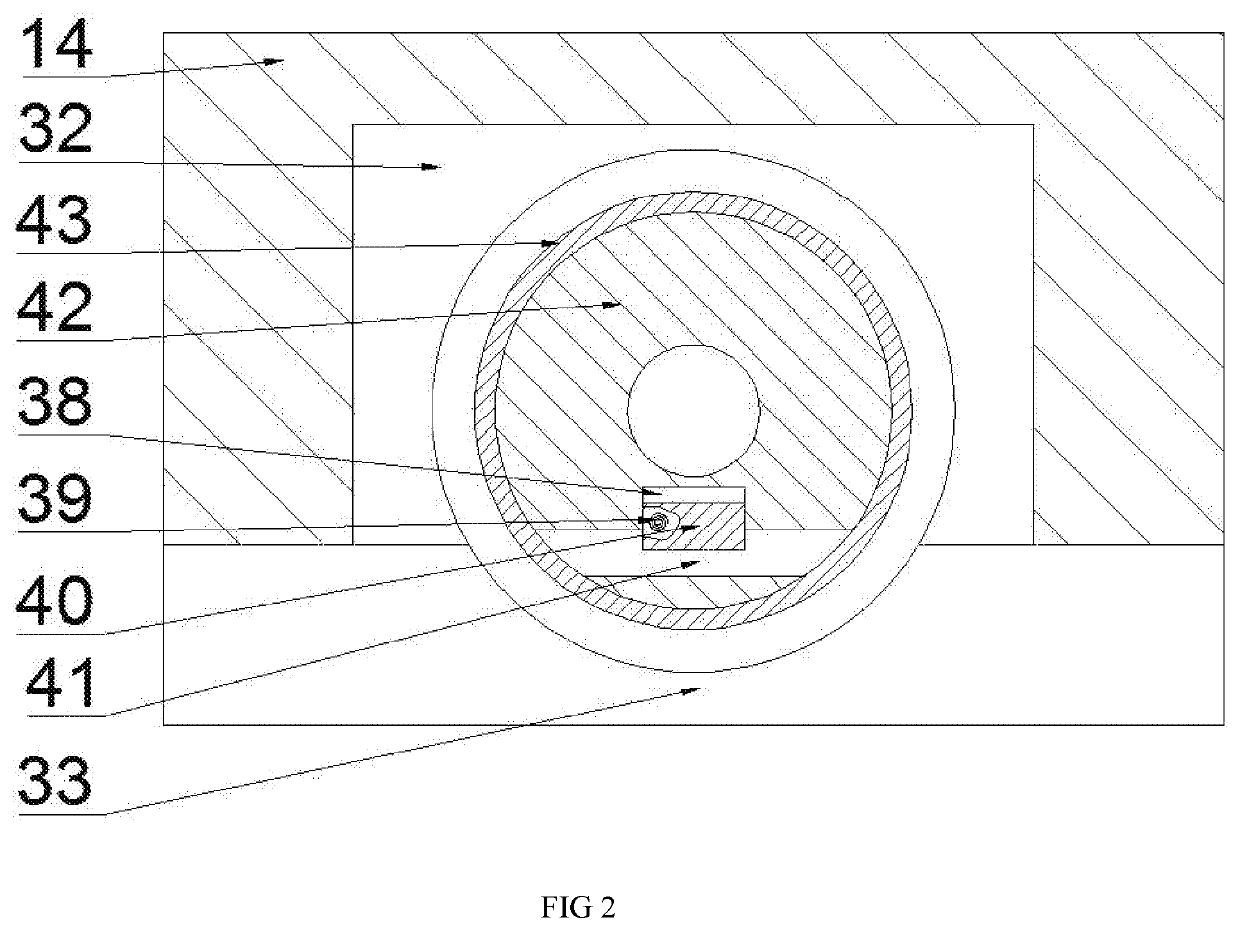
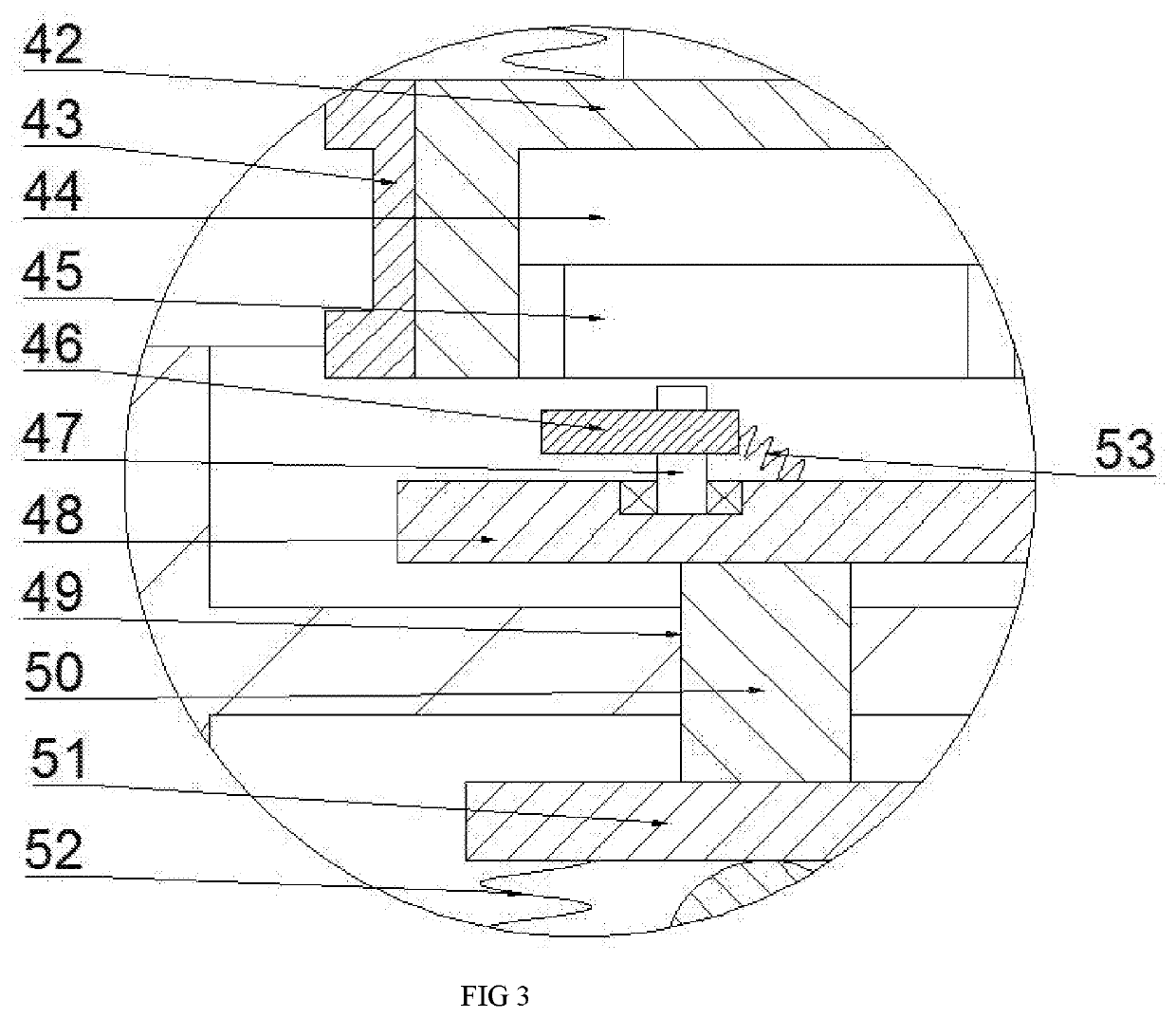
[0014]The present invention will be described in detail below with reference to FIGS. 1-3. Among them, for convenience of description, the orientation described below is specified as follows: the up-down, left-right, front-back direction described below is consistent with the up-down, left-right, front-back direction of the projection relationship of FIG.

[0015]As shown in FIGS. 1-3, a multifunctional hub of the present invention includes a box body14, which is provided with a sliding cavity 18 with an upward opening therein, and an annular slider 15 is slidably provided in the sliding cavity 18. The left and right sides of the ring slider 15 are provided with fixing blocks 11 symmetrically fixed on the left and right sides, and the handle 10 is fixed on the outer end surface of the fixing block 11 with locking teeth...


PUM


Abstract

A multifunctional hub according to the present invention includes a box body, and the box body is provided with a sliding cavity with an upward opening therein, and an annular slider is slidably slid in the sliding cavity. The multifunctional hub of the present invention has simple and clear operation, sensitive response, saving time and labor; at the same time, the device of the present invention is rich in functions, fixed and reliable, and highly practical.

Description

CROSS-REFERENCES TO RELATED APPLICATIONS[0001]The present application claims priority from Chinese application No. 201910348287X filed on Apr. 28, 2019 which is hereby incorporated by reference in its entirety.FIELD OF TECHNOLOGY[0002]The invention relates to the field of computer accessories, and in particular relates to a multifunctional hub.TECHNICAL FIELD[0003]In places such as homes and offices, many different wires are often required to shuttle between the desktop or the bottom. The wires are of different lengths and will be cluttered if they are not organized. This affects the appearance and is not conducive to replacing or changing the wires. General hubs require both hands. The wire is manually wound on the hub, and the general hub cannot be fixed, it is easy to move around, rub against the ground, and contaminate the dust; in addition, when the general hub is on the desktop, the function is single and takes up extra space; therefore, it is necessary to design a Multifuncti...

Claims


Application Information

Patent Timeline
IPC IPC(8): B65H75/48A47B21/06
CPCA47B21/06A47B2200/0082B65H75/486B02C13/02B02C13/30B02C19/20B02C21/00B08B3/102B08B13/00B65H75/40B65H75/4428B65H75/446B65H75/4492B65H2701/34
Inventor YANG, CUIFANG
Owner YANG CUIFANG
Why Eureka
Try Eureka