
Hydrogen supply control system and control method for fuel cell

a control system and fuel cell technology, applied in the direction of reactant parameter control, fuel cell, electrical apparatus, etc., can solve the problems of inability to maintain the hydrogen concentration of the fuel cell properly, the concentration of hydrogen cannot be optimally adjusted, and the purging performance may not be possible, so as to achieve the effect of ensuring the durability of the system, and reducing the difficulty of recirculation

Active Publication Date: 2020-05-07
HYUNDAI MOTOR CO LTD +1
View PDF0 Cites 5 Cited by
  • Summary
  • Abstract
  • Description
  • Claims
  • Application Information

AI Technical Summary

Benefits of technology

The hydrogen supply control system and control method for a fuel cell described in this patent make it more accurate to estimate the concentration of gas purged by a purge valve. This is done by reflecting the amount of gas recirculating in a recirculation line and accounting for the purge amount of each gas. This improves the accuracy of estimating the hydrogen concentration in the recirculation line and ensures the durability of the system. It also improves fuel efficiency by improving purge control.

Problems solved by technology

Therefore, criteria for a hydrogen target concentration or a hydrogen target pressure are not clear, and accordingly, a concentration of hydrogen is unable to be adjusted in an optimal manner.
In addition, the Q value is not increased where an output current of the fuel cell is zero (e.g., in an idle stop section) and thus, purging performance may not be possible.
In addition, the concentration of hydrogen of the fuel cell may not be maintained properly according to a driving situation such as driving in high speed or driving in a city (e.g., congested areas).
Accordingly, spread by the recirculation line is achieved insufficiently and thus, an effect of purging does not fully correspond to a state in which the recirculation effect is substantial.

Method used


Image

  • Hydrogen supply control system and control method for fuel cell
  • Hydrogen supply control system and control method for fuel cell

Examples


Embodiment Construction

[0020]It is understood that the term “vehicle” or “vehicular” or other similar term as used herein is inclusive of motor vehicles in general such as passenger automobiles including sports utility vehicles (SUV), buses, trucks, various commercial vehicles, watercraft including a variety of boats and ships, aircraft, and the like, and includes hybrid vehicles, electric vehicles, combustion, plug-in hybrid electric vehicles, hydrogen-powered vehicles and other alternative fuel vehicles (e.g. fuels derived from resources other than petroleum).

[0021]Although exemplary embodiment is described as using a plurality of units to perform the exemplary process, it is understood that the exemplary processes may also be performed by one or plurality of modules. Additionally, it is understood that the term controller / control unit refers to a hardware device that includes a memory and a processor. The memory is configured to store the modules and the processor is specifically configured to execute ...


PUM

PropertyMeasurementUnit
delay timeaaaaaaaaaa
gas constantaaaaaaaaaa
concentrationaaaaaaaaaa

Abstract

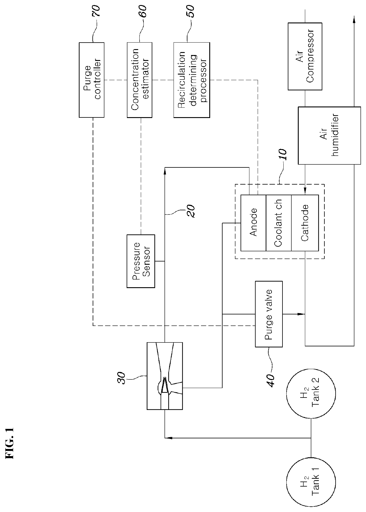
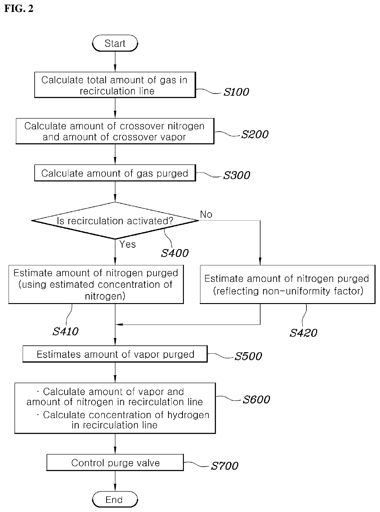
A hydrogen supply control system for a fuel cell is provided. The system includes a fuel cell stack that generates electricity using supplied hydrogen and air and a recirculation line that supplies hydrogen discharged from an outlet of the fuel cell stack back to an inlet of the fuel cell stack. A purge valve is disposed at an outlet side of the fuel cell stack of the recirculation line and discharges hydrogen in the recirculation line to the outside as the outlet is opened. A recirculation determining processor determines a recirculation state of the recirculation line and a concentration estimator estimates a purge amount for each gas, which is purged by the purge valve, based on the determined recirculation state and estimates a concentration of hydrogen in the recirculation line based on the estimated purge amount for each gas.

Description

CROSS REFERENCE TO RELATED APPLICATION[0001]The present application claims priority to Korean Patent Application No. 10-2018-0132992, filed Nov. 1, 2018, the entire contents of which is incorporated herein for all purposes by this reference.BACKGROUNDField of the Invention[0002]The present invention relates to a hydrogen supply control system and a control method for a fuel cell, and more specifically, to a technique that directly estimates a concentration of hydrogen supplied to a fuel cell stack and performs purge control and hydrogen pressure control.Description of the Related Art[0003]A fuel cell converts chemical energy, which is derived from an oxidation and reduction reaction of hydrogen and oxygen supplied by a hydrogen supplier and an air supplier, respectively, into electrical energy. A fuel cell includes fuel cell stacks that produce electrical energy and a cooling system for cooling the fuel cell stacks.[0004]Hydrogen is supplied to an anode side of a fuel cell, and an o...

Claims


Application Information

Patent Timeline
Patent Type & Authority Applications(United States)
IPC IPC(8): H01M8/04746H01M8/0444H01M8/04537H01M8/04082
CPCH01M8/04582H01M8/04201H01M8/04462H01M8/04761H01M8/04447H01M8/04089H01M8/04753H01M8/04097H01M8/04589H01M8/04805Y02E60/50H01M8/04231H01M8/0444H01M8/04992
Inventor KWON, SOON WOOLEE, JOON YONG
Owner HYUNDAI MOTOR CO LTD
Learn More