Redundancy system and method

a technology of redundancy plan and redundancy plan, which is applied in the direction of automatic control system, process and machine control, instruments, etc., can solve the problems of plurality of plural computing devices being incapable of operating autonomous vehicles, etc., and achieves lower speed operation and high speed operation

Active Publication Date: 2020-05-14
MAGNA ELECTRONICS
View PDF10 Cites 17 Cited by
  • Summary
  • Abstract
  • Description
  • Claims
  • Application Information

AI Technical Summary

Benefits of technology

[0007]One or more of the following features may be included. The nominal autonomous operational mode may include one or more of: operating the autonomous vehicle up to a full operational speed; utilizing a full obstacle detection range; allowing passing maneuvers; allowing unprotected turns across traffic; processing certain sensor data; allowing the use of higher risk routes; allowing the use of less-connected routes; allowing the use of routes lacking breakdown lanes / areas; utilizing a narrower definition of an obstacle to allow higher speed operation; and allowing the use of smaller buffers with respect to obstacles. The degraded autonomous operational mode may include one or more of: operating the autonomous vehicle up to a degraded operational speed; utilizing a degraded obstacle detection range; prohibiting passing maneuvers; prohibiting unprotected turns across traffic; not processing certain sensor data; prohibiting the use of higher risk routes; prohibiting the use of less-connected routes; prohibiting the use of routes lacking breakdown lanes / areas; utilizing a broader definition of an obstacle to require lower speed operation; requiring the use of larger buffers with respect to obstacles; requiring the vehicle to safely pull off of the road; and requiring the vehicle to call for assistance. A larger portion of the plurality of computing devices may be capable of operating the autonomous vehicle in the nominal autonomous operational mode. A smaller portion of the plurality of computing devices may be incapable of operating the autonomous vehicle in the nominal autonomous operational mode. The smaller portion of the plurality of computing devices may be capable of operating the autonomous vehicle in the degraded autonomous operational mode. The larger portion of the plurality of computing devices capable of operating the autonomous vehicle in the nominal autonomous operational mode may include all of the plurality of computing devices within the autonomous vehicle. The larger portion of the plurality of computing devices capable of operating the autonomous vehicle in the nominal autonomous operational mode may include some, but not all, of the plurality of computing devices within the autonomous vehicle. The autonomous vehicle may include a plurality of sensors. All of the plurality of sensors may be coupled to all of the plurality of computing devices. A first portion of the plurality of sensors may be coupled to a first computing system within the plurality of computing devices and at least a second portion of the plurality of sensors may be coupled to at least a second computing system within the plurality of computing devices.

Problems solved by technology

A smaller portion of the plurality of computing devices may be incapable of operating the autonomous vehicle in the nominal autonomous operational mode.

Method used


Image

  • Redundancy system and method
  • Redundancy system and method
  • Redundancy system and method

Examples


Embodiment Construction

[0020]Autonomous Vehicle Overview

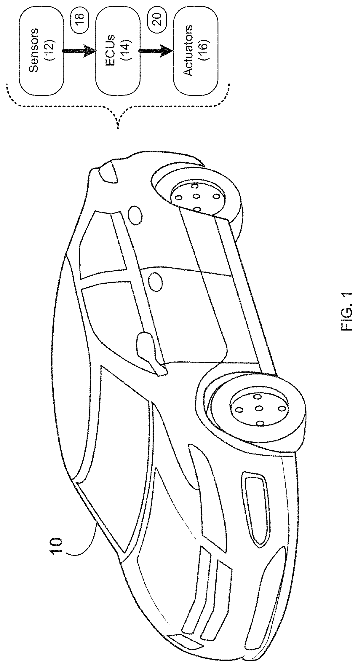
[0021]Referring to FIG. 1, there is shown autonomous vehicle 10. As is known in the art, an autonomous vehicle (e.g. autonomous vehicle 10) is a vehicle that is capable of sensing its environment and moving with little or no human input. Autonomous vehicles (e.g. autonomous vehicle 10) may combine a variety of sensor systems to perceive their surroundings, examples of which may include but are not limited to radar, computer vision, LIDAR, GPS, odometry, temperature and inertial, wherein such sensor systems may be configured to interpret lanes and markings on a roadway, street signs, stoplights, pedestrians, other vehicles, roadside objects, hazards, etc.

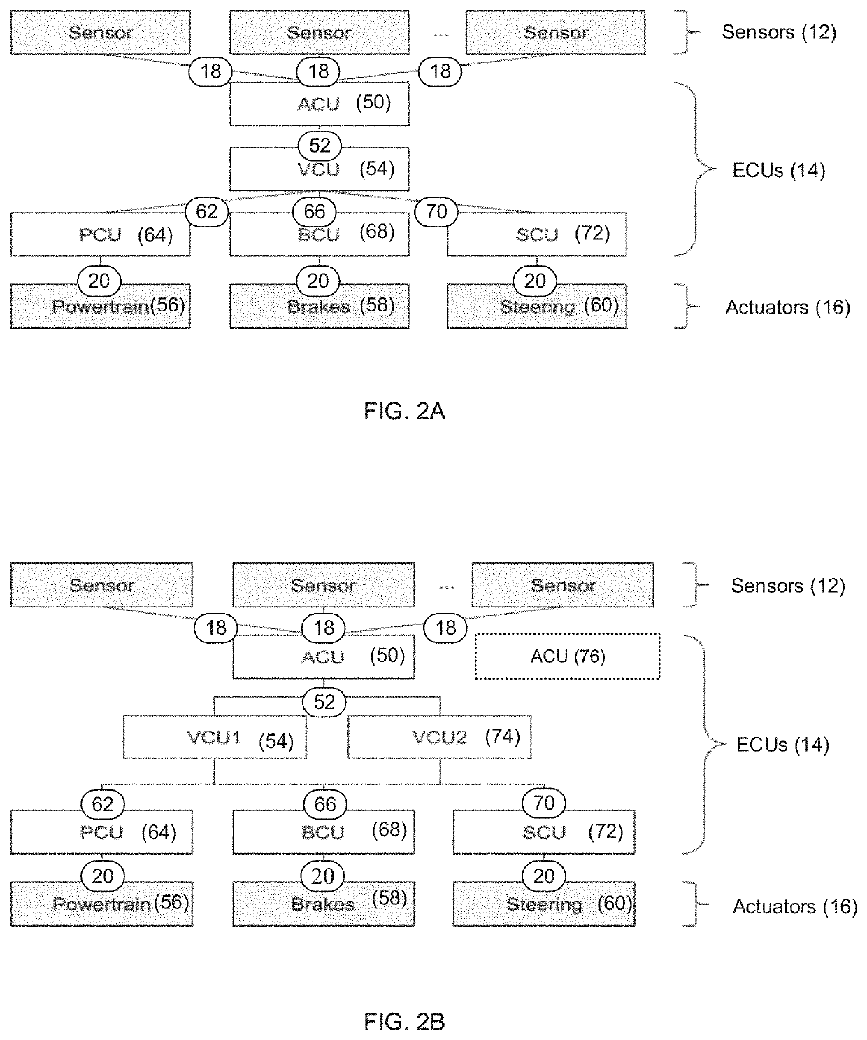
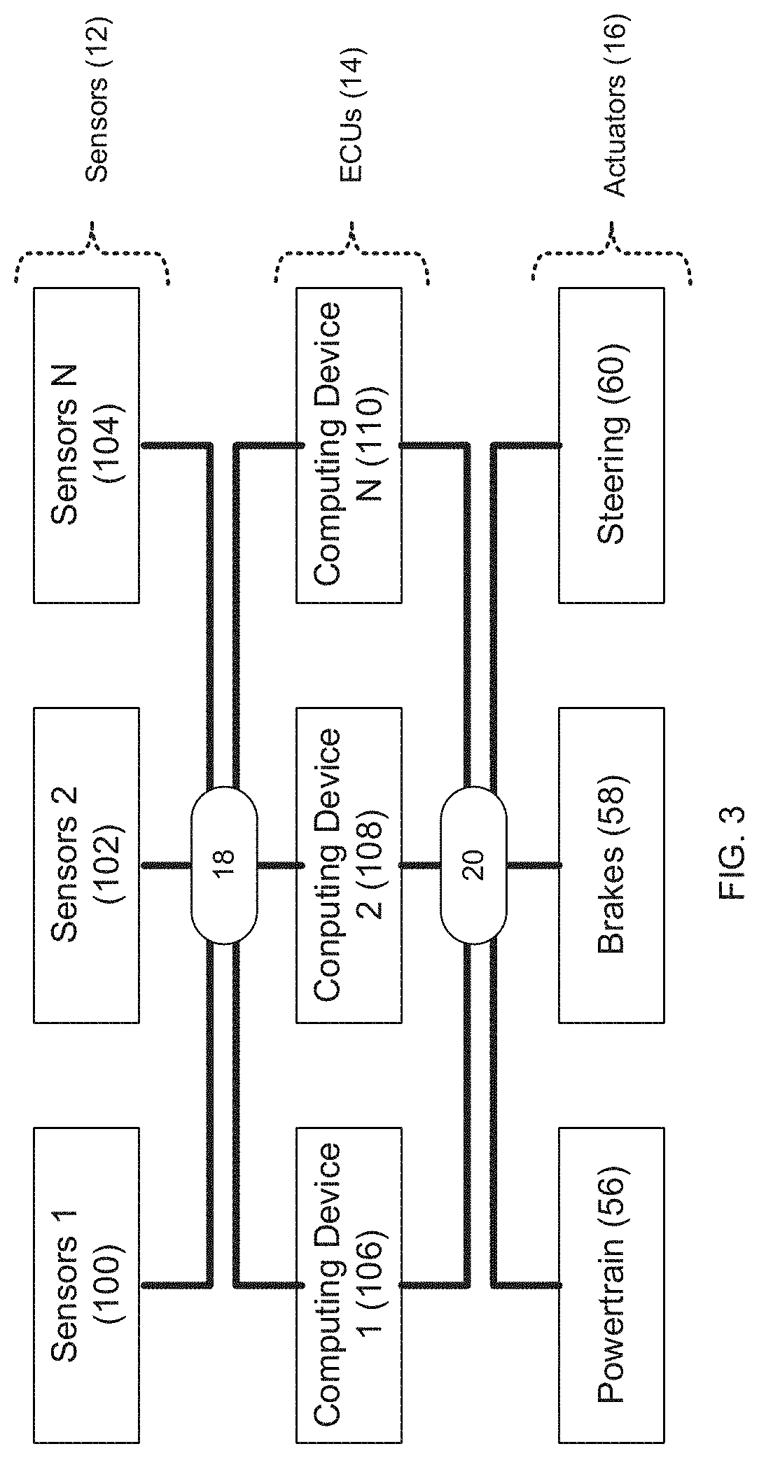
[0022]Autonomous vehicle 10 may include a plurality of sensors (e.g. sensors 12), a plurality of electronic control units (e.g. ECUs 14) and a plurality of actuators (e.g. actuators 16). Accordingly, sensors 12 within autonomous vehicle 10 may monitor the environment in which autonomous vehicle 10 is ...


PUM


Abstract

A method, computer program product, and computing system for operating an autonomous vehicle; monitoring the operation of a plurality of computing devices within the autonomous vehicle; and in response to detecting the failure of one or more of the plurality of computing devices, switching the autonomous vehicle from a nominal autonomous operational mode to a degraded autonomous operational mode.

Description

RELATED APPLICATION(S)[0001]This application claims the benefit of U.S. Provisional Application No. 62 / 760,575, filed on 13 Nov. 2018, the entire contents of which are incorporated herein by reference.TECHNICAL FIELD[0002]This disclosure relates to redundancy plans and, more particularly, to redundancy plans for use in autonomous vehicles.BACKGROUND[0003]As transportation moves towards autonomous (i.e., driverless) vehicles, the manufactures and designers of these autonomous vehicle must define contingencies that occur in the event of a failure of one or more of the systems within these autonomous vehicles.[0004]As is known, autonomous vehicles contain multiple electronic control units (ECUs), wherein each of these ECUs may perform a specific function. For example, these various ECUs may calculate safe trajectories for the vehicle (e.g., for navigating the vehicle to its intended destination) and may provide control signals to the vehicle's actuators, propulsions systems and braking...

Claims


Application Information

Patent Timeline
Patent Type & Authority Applications(United States)
IPC IPC(8): B60W50/029G05D1/00B60W30/18
CPCB60W2556/00G05D1/0088B60W50/029G05D1/0055G05D2201/0213B60W30/18B60W2050/0292B60W60/0018B60W60/00186B60W2720/10B60W2754/30B60W2754/20G06F11/0796G06F11/165G06F11/2038G06F11/2048G06F11/1428G06F11/3013G06F11/3089
Inventor HUANG, ALBERTKARAMAN, SERTACCHIN, RYAN C.C.LARIOS-BERLIN, JENNYALMEIDA, RAMIRO
Owner MAGNA ELECTRONICS
Why Eureka
Try Eureka