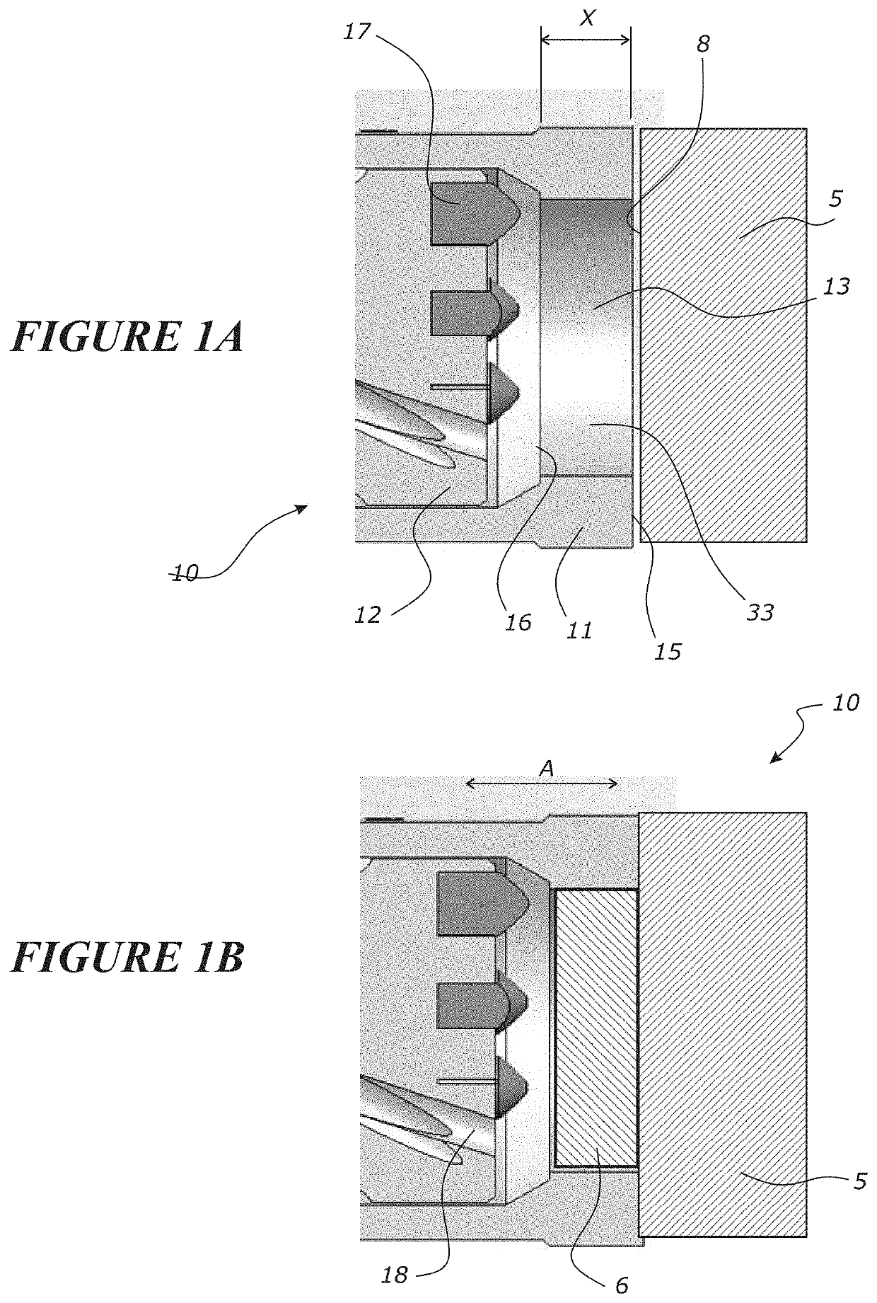
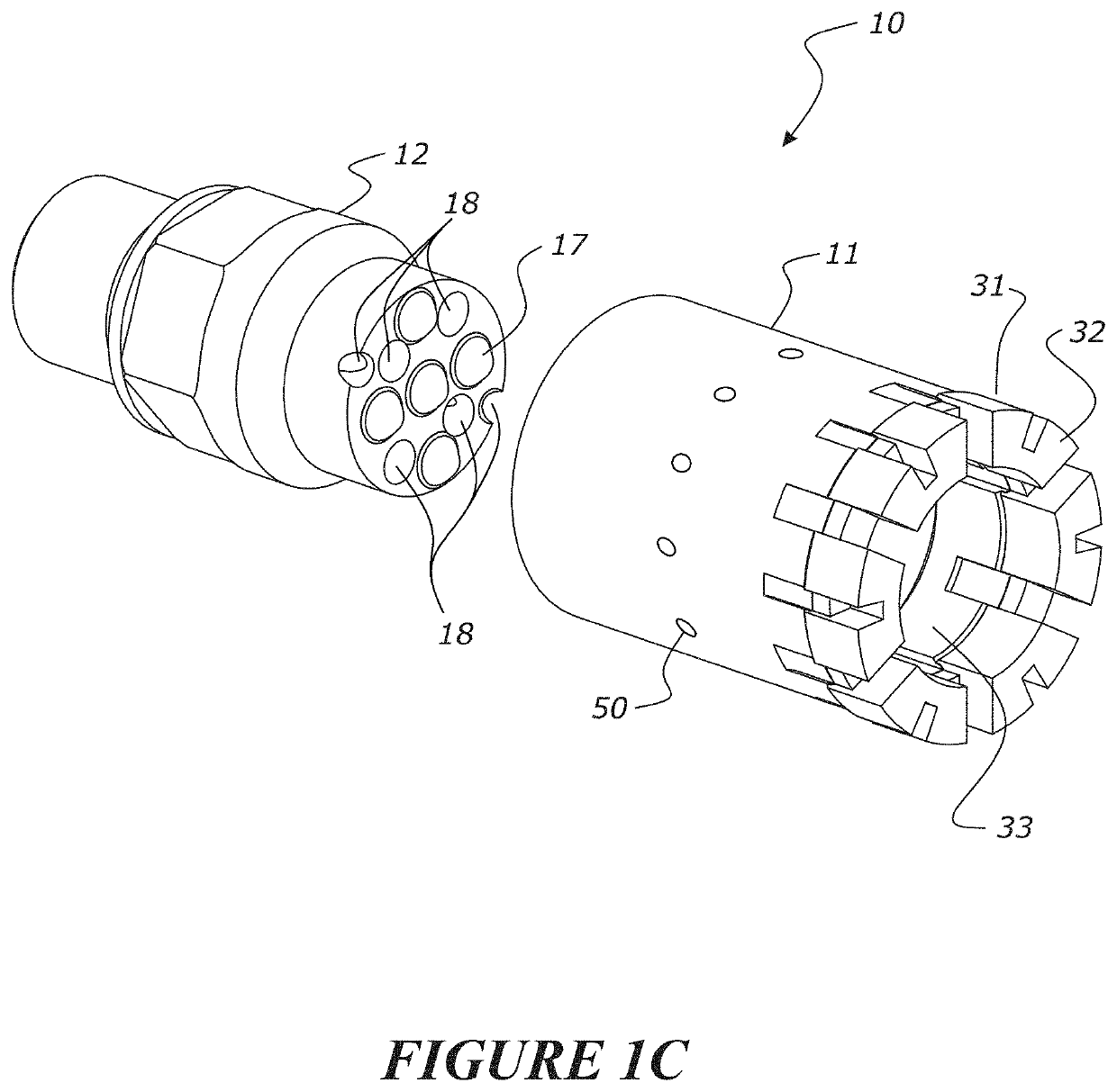
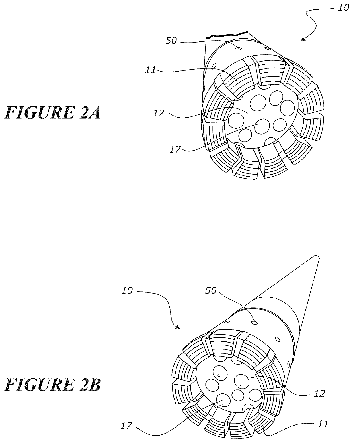
Hybrid drill bit
a hybrid drill bit technology, applied in drill bits, drilling accessories, earthwork drilling and mining, etc., can solve the problems of large compressors that are extremely expensive to operate, the volume of compressed air that needs to be pumped down deep holes becomes impractical, and the drilling speed is reduced, so as to improve drilling performance and reduce the speed of drilling. , the effect of improving the drilling speed
- Summary
- Abstract
- Description
- Claims
- Application Information
AI Technical Summary
Benefits of technology
Problems solved by technology
Method used
Image
Examples
second embodiment
[0070]An alternative (second) embodiment of the annular coring bit 11′ could be used in the hybrid drill bit instead. the annular coring bit 11′ and its assembly into a hybrid drill bit is shown in FIGS. 7 to 11. This embodiment is also for incorporation in / coupling to a reverse circulation (RC) drilling apparatus (such as shown in FIG. 4) for use in RC drilling field applications. It can also be used in boring applications (such as shown in FIG. 5A), with a slightly modified hybrid drill bit according to a variation of the embodiment, as shown in FIGS. 12 to 14, as will be described later.
[0071]The alternative annular coring bit 11′ is of a monobloc construction and can be assembled with the concentric coring bit 12 as shown in FIG. 10 to provide a hybrid drill bit 10′. This hybrid drill bit can be used in the same applications as the embodiment described above.
[0072]Referring first to FIG. 7, the annular coring bit 11′ of this embodiment is a monobloc structure comprising a body 7...
first embodiment
[0082]The annular coring bit 11′ can be assembled into a hybrid drill bit 10′ such as shown in FIG. 10, with the same benefits as previously described for the annular coring bit 11 of the first embodiment used in the hybrid drill bit.
[0083]FIG. 7 shows the annular core bit 11 in its virgin state before it is used for drilling. As the bit is used for drilling, it wears such that the cutting structure wears down as shown in FIGS. 9A to 9F. The cutting structure described is configured such that during wear it maintains at least some degree of mutual bracing between inner 74A and outer teeth 74B, and also maintains pathway for fluid flow, or at least reduces the disappearance of pathway for fluid flow. This will be explained further with reference to FIGS. 9A to 9F which show different stages of wear.
[0084]Referring to FIG. 9B after 5 mm of wear, it can be seen that some of the outer teeth 74B and inner teeth 74A have worn away such that they detach from the second corresponding inner / ...
PUM
 Abstract
Description
Claims
Application Information
 - R&D
- Intellectual Property
- Life Sciences
- Materials
- Tech Scout
- Unparalleled Data Quality
- Higher Quality Content
- 60% Fewer Hallucinations
Browse by: Latest US Patents, China's latest patents, Technical Efficacy Thesaurus, Application Domain, Technology Topic, Popular Technical Reports.
© 2025 PatSnap. All rights reserved.Legal|Privacy policy|Modern Slavery Act Transparency Statement|Sitemap|About US| Contact US: help@patsnap.com


